Earth working machine having a rotatable working apparatus axially positionally retainable with high tightening torque by means of a central bolt arrangement, and method for establishing and releasing such retention

a technology of axial position retention and working apparatus, which is applied in the direction of screws, threaded fasteners, ways, etc., can solve the problems of a1 being disadvantageous in terms of retaining effect, bolt arrangement beginning to loosen, and axial position retention of milling drum, etc., to achieve simple and reliable fashion and high tightening torque

Active Publication Date: 2022-04-26
WIRTGEN GMBH
View PDF23 Cites 0 Cited by
  • Summary
  • Abstract
  • Description
  • Claims
  • Application Information

AI Technical Summary

Benefits of technology

[0009]The object of the present invention is therefore to describe a technical teaching according to which the working apparatus is retainable in its axial position on the drive configuration by means of the central bolt arrangement, in simple and reliable fashion, with a high tightening torque.

Problems solved by technology

The axial positional retention of the milling drum relative to the drive configuration as known from DE 10 2012 008 252 A1 is disadvantageous in terms of its retaining effect.
Because of the use of a threaded rod screwed at the end into the drive configuration and a retaining nut in bolting engagement with the threaded rod, upon release of axial positional retention is not possible to predict the point at which the bolt arrangement begins to loosen upon exertion of a loosening torque (release moment).
In addition, because of the dimensions of the known retaining nut, the torque that can be exerted on the bolt arrangement of the known milling drum upon tightening and loosening using conventional tools, for example a torque wrench, is limited.
Applying such a large retaining torque to the bolt arrangement of the earth milling machine known from DE 10 2012 008 252 A1 is cumbersome, and requires tools that are usually available only in workshops but not at the utilization site of the machine.

Method used


Image

  • Earth working machine having a rotatable working apparatus axially positionally retainable with high tightening torque by means of a central bolt arrangement, and method for establishing and releasing such retention
  • Earth working machine having a rotatable working apparatus axially positionally retainable with high tightening torque by means of a central bolt arrangement, and method for establishing and releasing such retention
  • Earth working machine having a rotatable working apparatus axially positionally retainable with high tightening torque by means of a central bolt arrangement, and method for establishing and releasing such retention

Examples


second embodiment

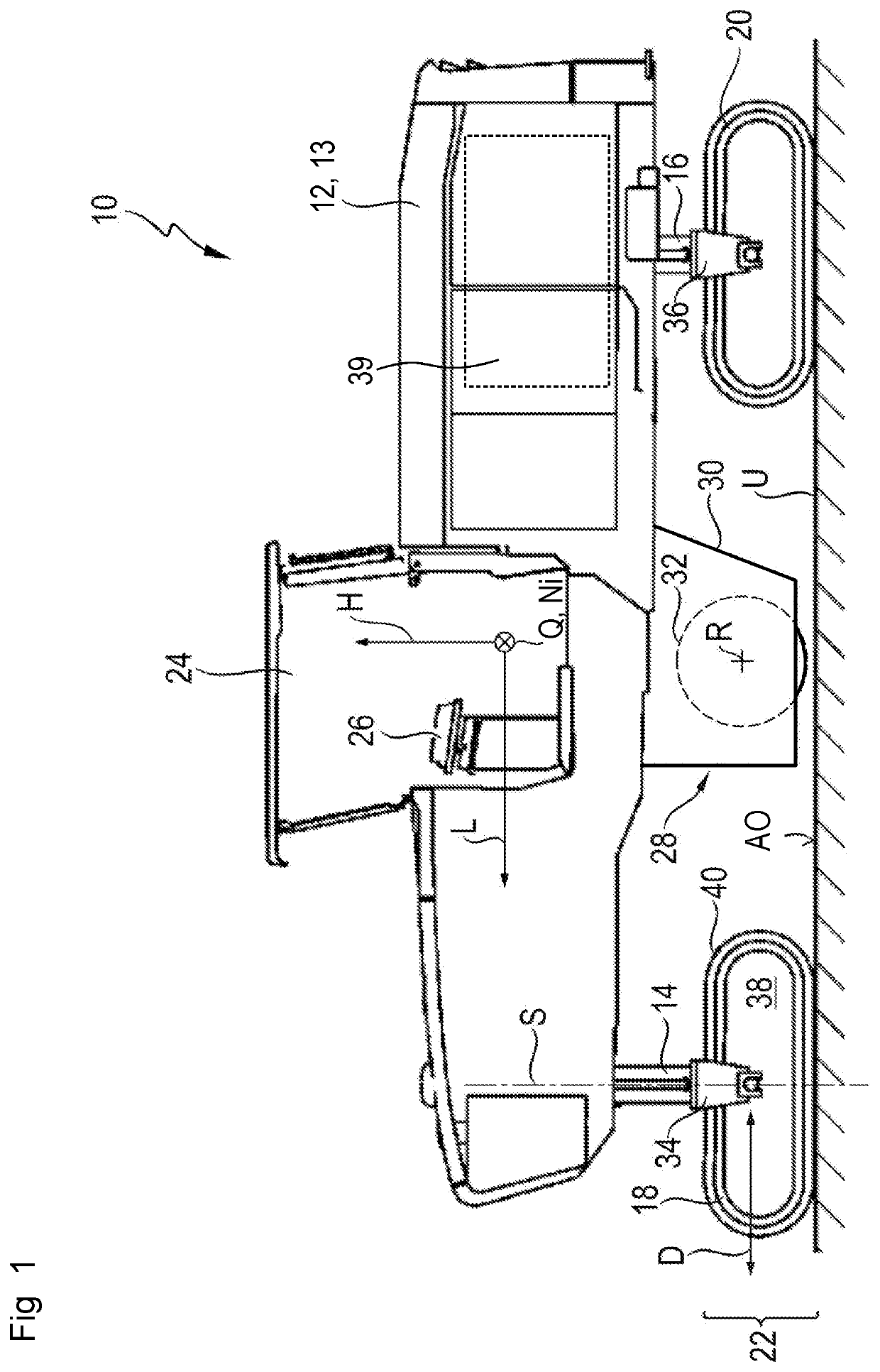
[0195]FIG. 7 shows working assembly 28.

[0196]Components and component portions identical and functionally identical to those in the first embodiment are labeled in the second embodiment with the same reference characters but incremented by 100. The second embodiment of FIG. 7 is explained below only insofar as it differs from the first embodiment to an extent essential in terms of the invention.

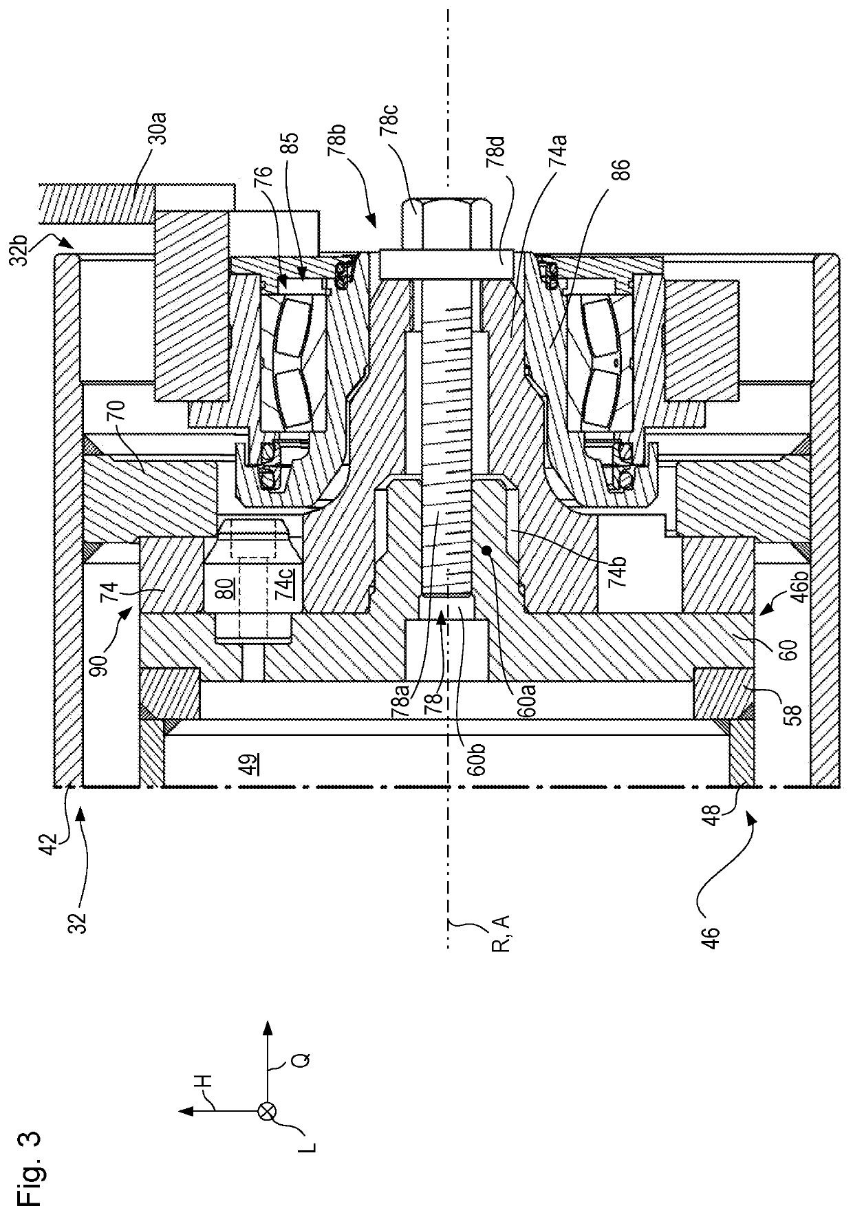
[0197]An essential modification of the second embodiment as compared with the previously described first embodiment is the conformation of centering stem 160a, which both acts as a centering configuration with respect to connecting flange 174 of milling drum 132 and serves as a bearing stem with respect to non-locating bearing 176.

first embodiment

[0198]Counterpart centering configuration 174b is thus once again embodied as a recess. In contrast to the first embodiment, in the second exemplifying embodiment centering stem 160a not only projects axially into connecting flange 174 but passes axially completely through it.

[0199]The result, as a consequence of the design, is that retaining bolt 178 can no longer impinge upon connecting flange 174 directly with axial force and displace it into the operating position, or retain milling drum 132 axially in the operating position via connecting flange 174. In the second embodiment, an axial force transfer between retaining bolt 178 and connecting flange 174 connected rigidly to milling drum 132 occurs with interposition of an auxiliary component 186 between bolt head 178b and connecting flange 174. Auxiliary component 186 is advantageously part of non-locating bearing 176, and serves in that context as a bracing component for the inner ring of the rolling bearing of non-locating bear...

third embodiment

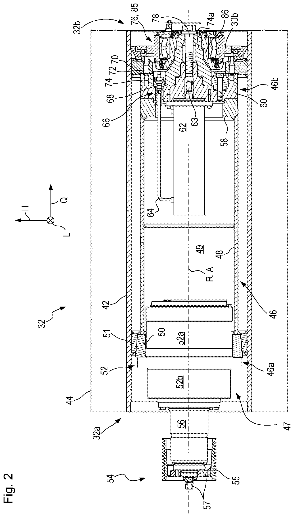
[0215]Lastly, FIG. 10 depicts a third embodiment that is intended simply to show that central retaining bolt 278 can also be bolted to piston rod 263 of hydraulic cylinder 262 for axial positional retention of milling drum 32 on drive configuration 46.

[0216]Components and component portions identical and functionally identical to those of the first embodiment are labeled in the third embodiment with the same reference characters but incremented by 200. The third embodiment of FIG. 10 will be explained here only insofar as it differs from the first embodiment to an extent essential in terms of the invention.

[0217]The third embodiment depicted in FIG. 10, having retaining bolt 278 threaded into piston rod 263, is of course also applicable to the design of the second embodiment in which centering stem 60a and bearing stem 74a are implemented in a single component. All that is then necessary is for bolt head 278b to brace against an auxiliary component that transfers force from bolt hea...


PUM


Abstract

A replaceable milling drum for an earth working machine includes a milling drum tube and a protrusion structure fixed to the milling drum tube. A bearing stem protrudes from the protrusion structure axially away from a drive axial end of the milling drum tube. The bearing stem has an outer surface including at least first and second cylindrical bearing surfaces axially spaced from each other, a furthest one of the cylindrical bearing surfaces from the drive axial end having a smaller diameter than a next furthest one of the cylindrical bearing surfaces from the drive axial end, the bearing stem having a central opening therethrough co-axial with the drive axis.

Description

BACKGROUND OF THE INVENTION[0001]The present invention relates to an earth working machine, such as a road milling machine, a recycler, a stabilizer, or a surface miner and the like. The earth working machine encompasses a machine body having a machine frame and a drive configuration rotationally drivable around a drive axis relative to the machine frame. The drive axis defines an axial direction. The earth working machine further encompasses a working apparatus for earth working to which the drive configuration is releasably connected in drive torque-transferring fashion for rotation together. The working apparatus extends axially between a drive axial end and a retention axial end located oppositely from the drive axial end, and radially externally surrounds the drive configuration of the earth working machine. The working apparatus is retained on the drive configuration, against axial displacement relative to the drive configuration, by way of a central bolt arrangement that is a...

Claims


Application Information

Patent Timeline
Patent Type & Authority Patents(United States)
IPC IPC(8): E01C23/088E01C23/12E21C47/00E21C35/193F16B19/02F16B37/14F16B39/02
CPCE01C23/088E01C23/127E21C35/193E21C47/00F16B19/02F16B37/14F16B39/02E01C21/00
Inventor BERNING, CHRISTIANBUHR, KARSTENFRANKEMÖLLE, MARKUSLEHNERT, THOMASSALZ, ANDREASWILHELMI, HARDY
Owner WIRTGEN GMBH
Why Eureka
Try Eureka