
Ear canal hologram for hearing apparatuses

a hearing apparatus and hologram technology, applied in the field of recording equipment, can solve the problems of high cost of scanners, requiring a complex system adjustment, and almost exclusively based scanners, and achieve the effect of high-quality hologram

Inactive Publication Date: 2010-09-14
SIEMENS AUDIOLOGISCHE TECHN
View PDF15 Cites 4 Cited by
  • Summary
  • Abstract
  • Description
  • Claims
  • Application Information

AI Technical Summary

Benefits of technology

"The present invention relates to a recording apparatus for recording the spatial structure of at least one part of an ear canal using holography. The apparatus includes a holography unit with a light source and a recording sensor for recording an object beam, which is produced by reflection of the illumination beam onto the ear canal. The apparatus can be calibrated and can produce a high-quality hologram for the actual measurements and production of a hearing apparatus. The technical effects of the invention include a simple and reliable method for recording the spatial structure of the ear canal and the ability to produce a housing shell or otoplastic for a hearing apparatus using the hologram of the ear canal."

Problems solved by technology

These scanners, like those used to record an ear impression, are relatively expensive and are almost exclusively based on triangulation measurement methods, which necessitate precise optical systems and also require a complex system adjustment.

Method used


Image

  • Ear canal hologram for hearing apparatuses
  • Ear canal hologram for hearing apparatuses
  • Ear canal hologram for hearing apparatuses

Examples


Embodiment Construction

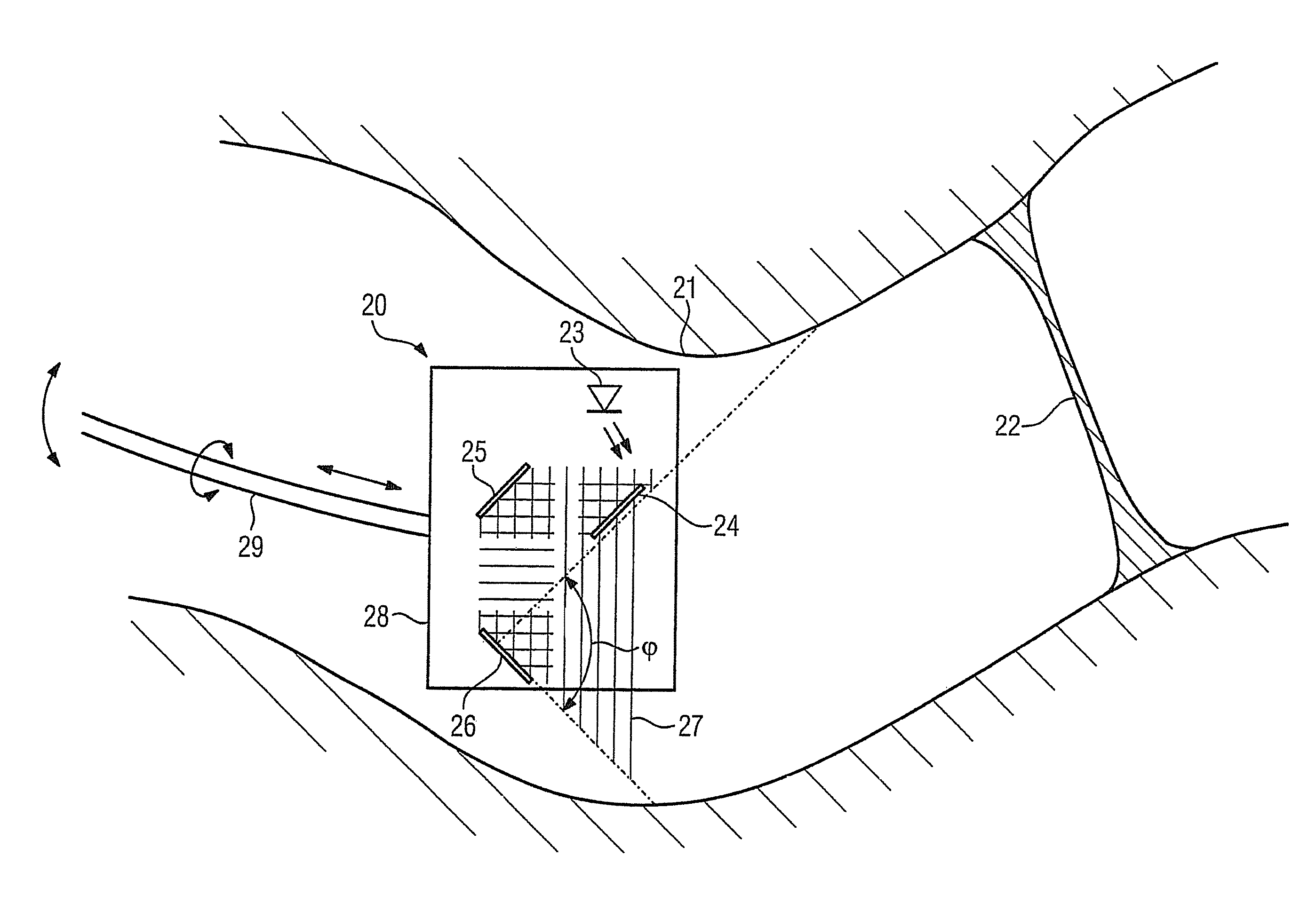
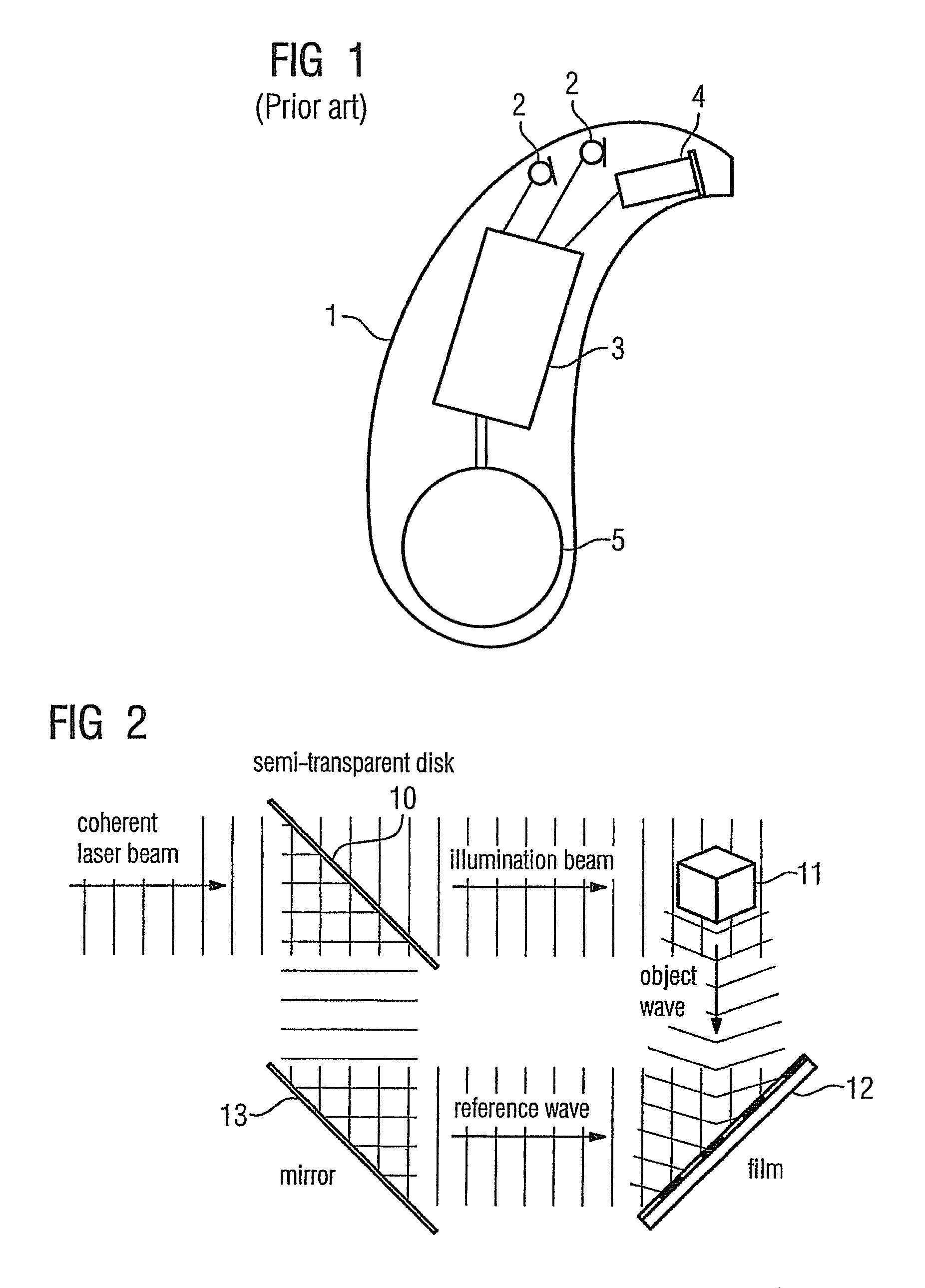
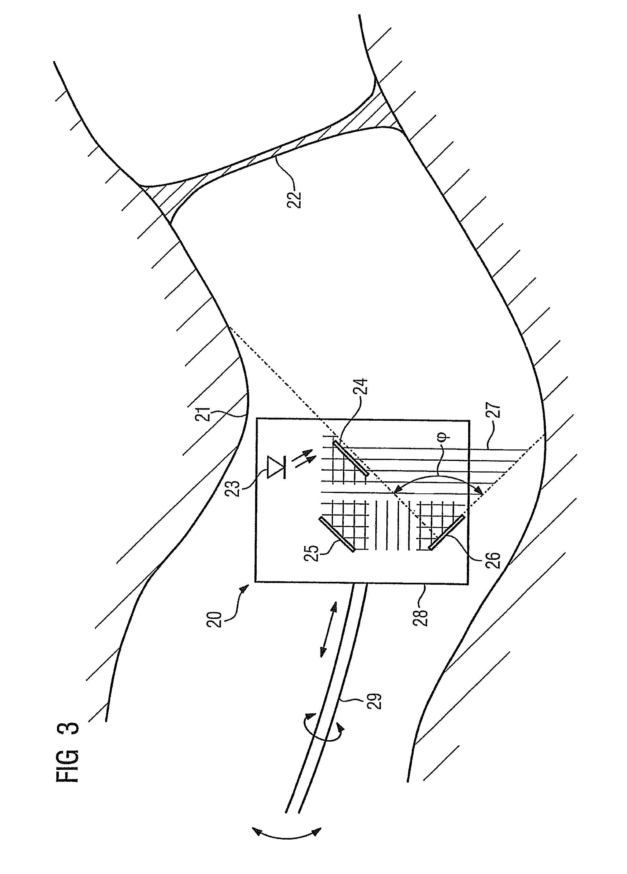
[0026]The exemplary embodiment illustrated in more detail below represents a preferred embodiment of the present invention. The principle behind holography is however first explained in brief on the basis of FIG. 2, in order to gain a better understanding of the structure of the inventive device in accordance with FIG. 3.

[0027]In accordance with FIG. 2, a coherent laser beam is sent to a semi-transparent disk 10 in order to obtain a hologram. One part of the laser beam penetrates the semi-transparent disk and forms an illumination beam, which strikes the object 11, here the ear canal or the ear impression. One part of the illumination beam is reflected onto the object 11 and forms an object wave, which hits a film 12. At the same time, one part of the coherent laser beam is deflected for this purpose by the semi-transparent disk onto a mirror 13 and from there further onto the film 12 as a reference source. The object wave overlaps the reference wave on the film 12, thereby resultin...


PUM

PropertyMeasurementUnit
semi-transparentaaaaaaaaaa
spatial structureaaaaaaaaaa

Abstract

The aim is to be able to determine the spatial structure of an ear canal in a simple and reliable fashion. To this end, it is proposed to produce a hologram of the ear canal, by inserting a holography unit at least partially into the ear canal. The data for the shape of a housing shell or an otoplastic can then be obtained from the resulting hologram for automatic manufacturing methods.

Description

CROSS REFERENCE TO RELATED APPLICATIONS[0001]The present application claims the benefit of the provisional patent application filed on Dec. 4, 2006, and assigned application No. 60 / 872,762, which is incorporated by reference herein in its entirety.FIELD OF THE INVENTION[0002]The present invention relates to a recording apparatus for recording the spatial structure of at least one part of an ear canal or ear impression. The present invention also relates to a facility for producing a housing shell or an otoplastic for a hearing apparatus as well as a corresponding recording method and a production method. Hearing apparatus is understood here to mean in particular a hearing device, but also a headset, headphones or suchlike.[0003]Hearing devices are wearable hearing apparatuses used to assist the hard-of-hearing. To meet the numerous individual requirements, different designs of hearing device are provided, such as behind-the ear (BTE) hearing devices, in-the-ear (ITE) hearing devices...

Claims


Application Information

Patent Timeline
Patent Type & Authority Patents(United States)
IPC IPC(8): G01B9/021
CPCA61B5/1075A61B5/1079A61B5/6817G03H1/0005G03H1/02H04R25/70A61B5/0059G03H2001/0033G03H2001/0038G03H2001/0204G03H2210/30G03H2226/11G03H2227/02
Inventor REITHINGER, JURGEN
Owner SIEMENS AUDIOLOGISCHE TECHN
Learn More