Adjustable return roller bracket for tracking conveyor belts

a technology of return roller and tracking conveyor, which is applied in the direction of rollers, conveyor parts, packaging, etc., can solve the problems of misalignment of conveyor belts with pulleys and rollers, affecting the operation of belt conveyor systems, and conveyor belts

Active Publication Date: 2022-05-17
PRECISION
View PDF4 Cites 0 Cited by
  • Summary
  • Abstract
  • Description
  • Claims
  • Application Information

AI Technical Summary

Benefits of technology

[0007]Another possible non-limiting object of the present invention is to provide an adjustable roller bracket assembly for use with a belt conveyor system, and which may permit for tracking a conveyor belt without necessarily requiring operation of the belt conveyor system to pause or stop during tracking.
[0036]It has been appreciated that during normal operation of the belt conveyor system, the conveyor belt may move laterally (i.e., normal to a moving direction of the conveyor belt in the endless loop) towards an axial end of the roller, thus requiring realignment or tracking of the conveyor belt to prevent system failure or damage. It has also been appreciated that if, for example, the conveyor belt has moved laterally towards a first axial end of the roller, the rotational axis of the roller may be adjusted with the selective movement of the second end portion relative to the first end portion, such that the first axial end contacts the conveyor belt in the moving direction before the opposite second axial end. The applicant has appreciated that the adjustable roller bracket assembly may advantageously permit operation to track the conveyor belt without necessarily ceasing operation of the belt conveyor system while the conveyor belt is moving in the endless loop, and at a safe distance from the conveyor belt while visually inspecting alignment.

Problems solved by technology

During operation of the belt conveyor system, the conveyor belt may move laterally off the normal direction of travel in the endless loop, and become misaligned with the pulleys and the rollers.
If left uncorrected, the conveyor belt may possibly run off the pulleys and the rollers, and negatively affect operation of the belt conveyor system.

Method used


Image

  • Adjustable return roller bracket for tracking conveyor belts
  • Adjustable return roller bracket for tracking conveyor belts
  • Adjustable return roller bracket for tracking conveyor belts

Examples


Embodiment Construction

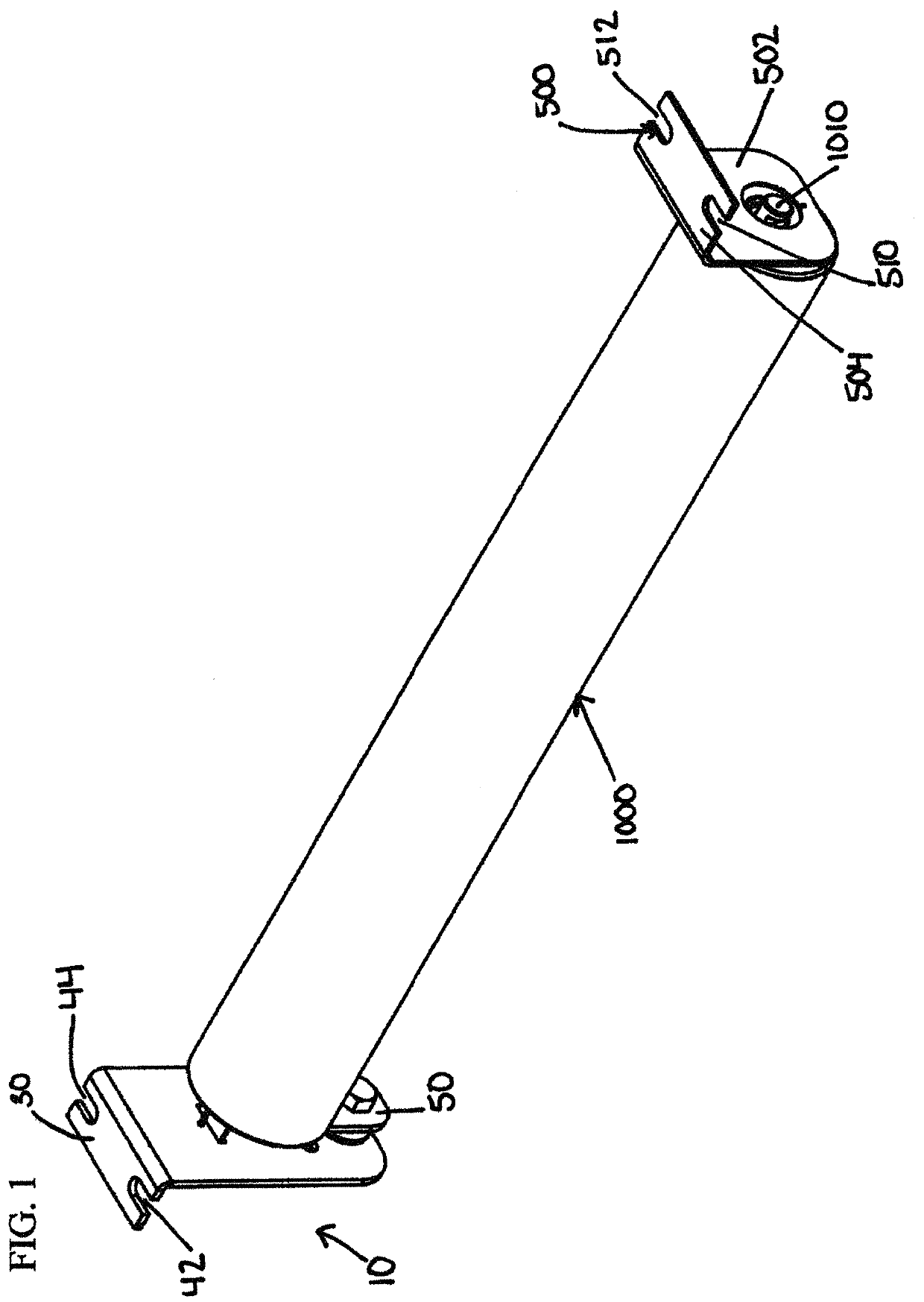
[0050]Reference is made to FIG. 1 which shows a perspective view of an adjustable return roller bracket assembly 10 in an operable position with a nonadjustable return roller bracket assembly 500 to rotatably engage a return roller 1000 included with a belt conveyor system (not shown). In the construction shown, and as will be further described below, the bracket assembly 10 broadly includes a frame attachment plate 30, a roller engagement plate 50, a coupling bolt 70 and a retention or locking bolt 90.

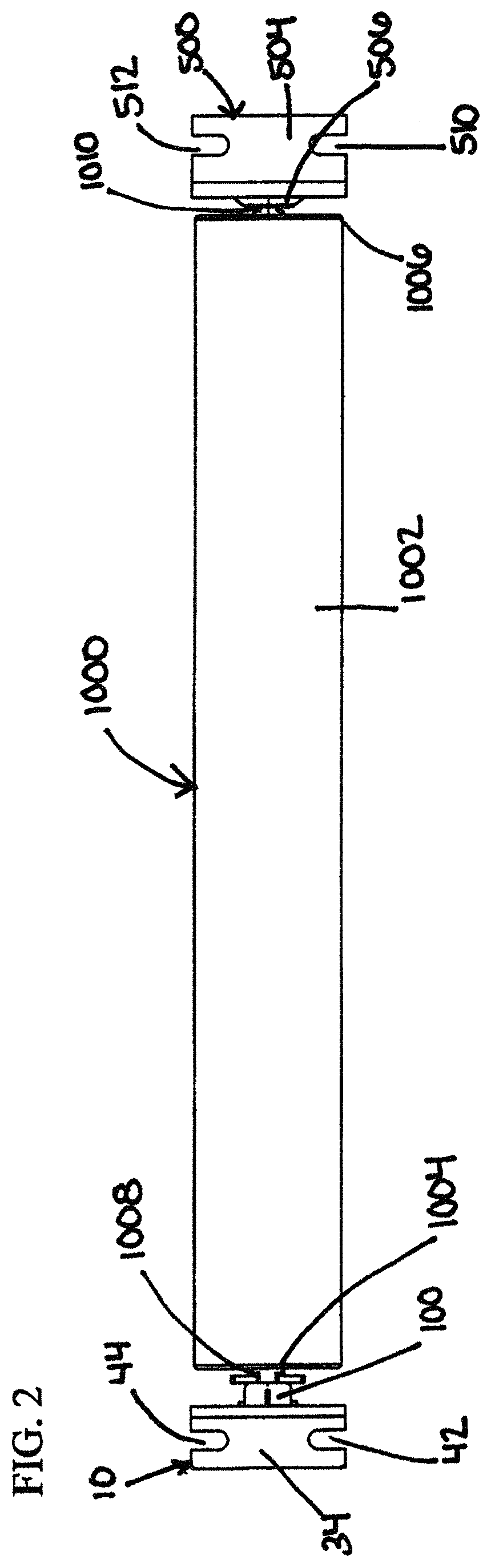
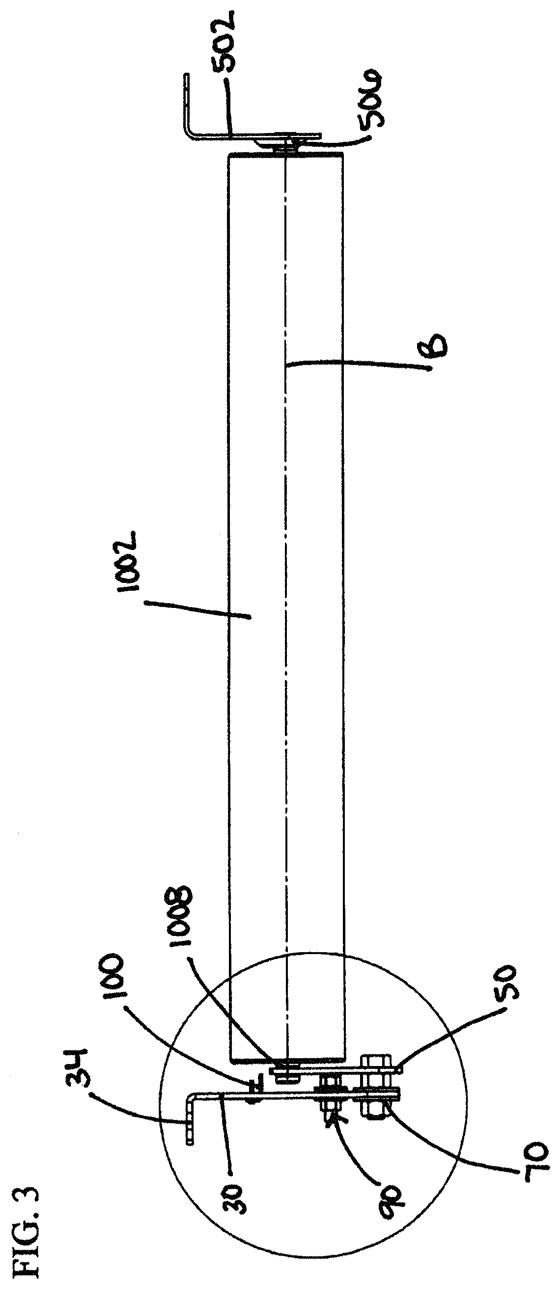
[0051]As best seen in FIGS. 2 and 3, the return roller 1000 includes an elongate cylindrical body 1002 having a pair of opposed axial ends 1004, 1006. The axial ends 1004, 1006 rotatably retain at a center roller pins 1008, 1010, respectively, which extends outwardly therefrom to connect with the assemblies 10, 500, as will be further described below. As seen in FIG. 3, the roller pins 1008, 1010 are aligned with a rotational axis B of the return roller 1000.

[0052]Reference is made to...


PUM


Abstract

In a preferred embodiment, there is provided an adjustable roller bracket assembly for a belt conveyor system, and which comprises a first end portion, a second end portion, and an adjustment mechanism connecting the first and second end portions, the first end portion being for attachment to a system frame, the second end portion being for rotatably engaging a roller at an axial end thereof, and the adjustment mechanism being operable to permit selective movement of the second end portion relative to the first end portion against frictional resistance therebetween to effect adjustment of a rotational axis of the roller.

Description

SCOPE OF THE INVENTION[0001]The present invention relates to an adjustable roller bracket assembly for tracking a conveyor belt forming part of a belt conveyor system, and which are provided with first and second end portions and an adjustment mechanism connecting the first and second end portions.BACKGROUND OF THE INVENTION[0002]A belt conveyor system is a type of conveyor systems designed to move an object from one location to another location. At a simpler level, a belt conveyor system may include a frame, a pair of pulleys rotatably coupled to the frame at opposed frame ends and an endless loop of a conveyor belt disposed between and over the pulleys, where one or both of the pulleys are drive pulleys for moving the conveyor belt. In this configuration, the conveyor belt traverses from a first one of the pulleys to a second pulley (above the pulleys) in a conveying direction, over an outer periphery of the second pulley, traverses in a return direction opposite to the conveying ...

Claims


Application Information

Patent Timeline
Patent Type & Authority Patents(United States)
IPC IPC(8): B65G39/12B65G15/60
CPCB65G39/12B65G15/60B65G2207/30B65G39/16
Inventor BOIRE, STEVEN ARMAND
Owner PRECISION
Why Eureka
Try Eureka