
Method for offset calibration of a yaw rate sensor signal of a yaw rate sensor, system and computer program

a technology of yaw rate sensor and offset calibration, which is applied in the direction of acceleration measurement using interia forces, instruments, data processing applications, etc., can solve the negative effect of orientation estimation, 180° orientation errors can quickly occur within a few minutes, and not produce the desired offset correction effect, etc., to achieve rapid and reliable offset correction

Active Publication Date: 2022-05-17
ROBERT BOSCH GMBH
View PDF10 Cites 0 Cited by
  • Summary
  • Abstract
  • Description
  • Claims
  • Application Information

AI Technical Summary

Benefits of technology

[0006]An object of the present invention is to furnish a method for offset calibration of a rotation rate sensor signal of a rotation rate sensor which makes possible rapid and reliable offset correction for different utilization environments of a rotation rate sensor.
[0007]The method according to the present invention for offset calibration of a rotation rate sensor signal of a rotation rate sensor, in accordance with an example embodiment, may have the advantage as compared with the related art that the filter parameter is adapted to the idle-state conditions of the rotation rate sensor. It is, thus, possible to ascertain and use a different filter parameter, for example, for a rotation rate sensor that is (almost) entirely motionless in the idle state than for a sensor that is still exposed to slight movements and fluctuations even in the idle state. Even for a single sensor, the filter can advantageously be adapted to the instantaneous conditions of the idle state. It is correspondingly possible for the filtering time to be adapted to the idle-state conditions and thereby optimized. For example, a shortened time for offset ascertainment can thus be used for an (entirely) motionless sensor with low noise, with the result that a more precise correction and adaptation to changing temperature conditions can be achieved. For a sensor that is still exposed to considerable movement even in the idle state, conversely, by way of the ascertainment of the filter parameter it is possible to increase the time for offset ascertainment in order to better compensate for increased noise and, here as well, arrive at an appropriate offset correction.
[0019]Because of the fact that in the third step, the filtered measured rotation rate sensor value is furthermore ascertained, in particular with the aid of an exponential smoothing, as a function of a previous filtered measured rotation rate sensor value and of an instantaneous measured rotation rate sensor value, according to an embodiment of the present invention it is possible to achieve a particularly advantageous offset calibration.
[0021]Because of the fact that after the third step an output rate, in particular a sampling rate, of the filtered measured rotation rate sensor values is reduced with the aid of a decimator device so that reduced-output-rate filtered measured rotation rate sensor values are generated, according to an embodiment of the present invention it is possible for the output rate of the offset to be capable of being reduced and, in particular, to be independent of the measurement rate or sampling rate of the measured rotation rate sensor values.
[0023]According to an embodiment of the present invention, it is possible for the third step, preferably the second and the third step, particularly preferably the first, the second, and the third step, more preferably the first, the second, the third, and the fourth step, and even more preferably the first, the second, the third, the fourth, and the fifth step, to be repeated several times, in particular in such a way that a plurality of filtered measured rotation rate sensor values are generated in the third steps. Continuous adaptation of the offset calibration is thereby possible.

Problems solved by technology

This results in systematic errors, in particular drifts, when the rotation rate sensor signal is integrated, which have a negative effect on orientation estimation.
Orientation errors of 180° can quickly occur within a few minutes.
Because the offsets can change during operation of the sensor and over its lifetime, for example as a result of temperature influences, factory precalibration in the context of manufacture of the sensor generally does not produce the desired avoidance of offsets.
Conventional methods are disadvantageous, however, in that in some cases they are difficult and expensive to implement and, for example, require the presence of several different types of sensors on one chip system.
On the other hand, with many conventional systems it is difficult or even impossible to enable efficient offset correction for rotation rate sensors in different utilization environments, for example rotation rate sensors in a mobile telephone, which typically is regularly placed immovably on a desk or the like, and a rotation rate sensor in a wearable which, even in its idle position, is still exposed to considerable noise due to slight movements by the wearer.

Method used


Image

  • Method for offset calibration of a yaw rate sensor signal of a yaw rate sensor, system and computer program

Examples


Embodiment Construction

[0030]In the various Figures, identical parts are always labeled with the same reference characters and are therefore as a rule also each mentioned or named only once.

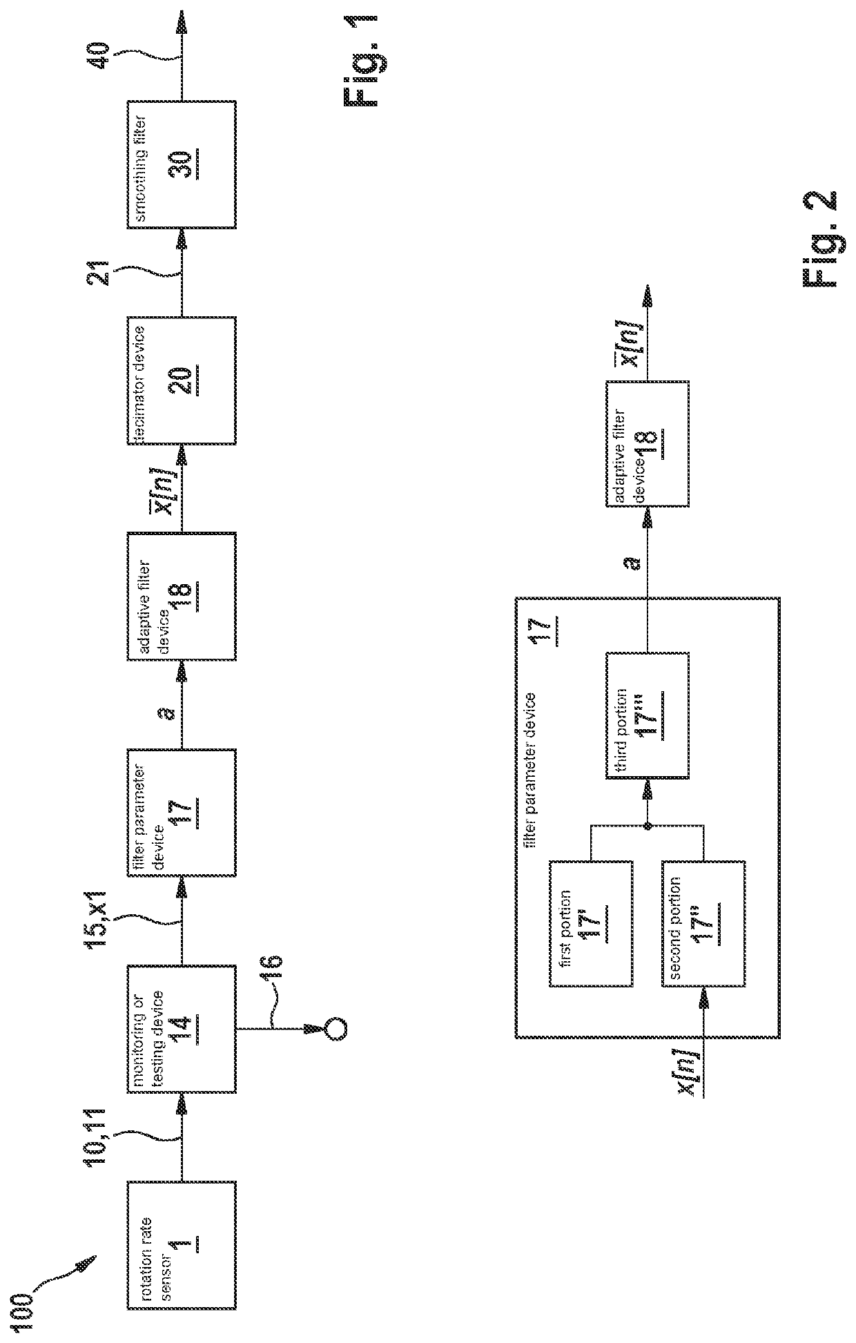
[0031]FIG. 1 is a schematic block diagram of a system 100 for offset calibration of a rotation rate sensor signal 11 of a rotation rate sensor 1, according to an embodiment of the present invention. A rotation rate sensor 1 supplies a rotation rate sensor signal 11 that encompasses a sequence of measured rotation rate sensor values 10. That signal is made available to a monitoring device 14 or testing device 14. Monitoring device 14 identifies, on the basis of measured rotation rate sensor values 10 that have been obtained, whether rotation rate sensor 1 is in an idle state 15 or in a non-idle state 16 or movable state 16. For this, monitoring device 14 estimates an estimated average of measured rotation rate sensor values 10 and an estimated fluctuation value, in particular an estimated variance, of measured rotation ...


PUM


Abstract

A method for offset calibration of a rotation rate sensor signal of a rotation rate sensor. In a first step, an ascertainment is made that the rotation rate sensor is in an idle state. In a second step, after the first step, a filter parameter is determined as a function of the measured rotation rate sensor values, measured in the idle state, of the rotation rate sensor. In a third step, after the second step, a filtered measured rotation rate sensor value is determined with the aid of the filter parameter. An offset is determined with the aid of the filtered measured rotation rate sensor value.

Description

FIELD[0001]The present invention relates to a method for offset calibration of a rotation rate sensor signal of a rotation rate sensor. The present invention further relates to a system for calibrating an offset of a rotation rate sensor signal of a rotation rate sensor, and to a computer program encompassing instructions.BACKGROUND INFORMATION[0002]Rotation rate sensors, in particular having microelectromechanical systems, are used in a wide variety of sectors. They are utilized, for example, in the field of electronic consumer goods as part of smartphones or so-called “wearables.” With them, the orientation of the device in space can be determined, the rotation rate sensor signal usually being integrated for that purpose. When the rotation rate sensor is in the motionless state, the rotation rate sensor signal should be zero. Typically, however, such rotation rate sensors have production-related offsets in their signals. This results in systematic errors, in particular drifts, whe...

Claims


Application Information

Patent Timeline
Patent Type & Authority Patents(United States)
IPC IPC(8): G01P15/08G01D1/16G06F17/17G01D1/18G06F17/18H03H17/06H04B1/00G06Q10/04G01D1/02G06F17/10H04L43/028G01D1/12H03H17/04
CPCG01P15/0802G01D1/02G01D1/12G01D1/16G01D1/18G06F17/10G06F17/17G06F17/18G06F2201/805G06Q10/04H03H17/045H03H17/0664H04B1/0021H04B1/0046H04L43/028G01C25/005G01C19/5776
Inventor BECKER, HANNAGUT, JUERGEN
Owner ROBERT BOSCH GMBH
Learn More