Ear splint to correct congenital ear deformities

a technology for congenital ear deformities and ear splints, which is applied in the field of congenital ear deformities, can solve the problems of lack of appearance and functionality, high cost of surgery, and trauma to children, and achieves the effect of convenient maintenance and placement, and high security and comfor

Active Publication Date: 2022-05-24
RGT UNIV OF MICHIGAN
View PDF21 Cites 0 Cited by
  • Summary
  • Abstract
  • Description
  • Claims
  • Application Information

AI Technical Summary

Benefits of technology

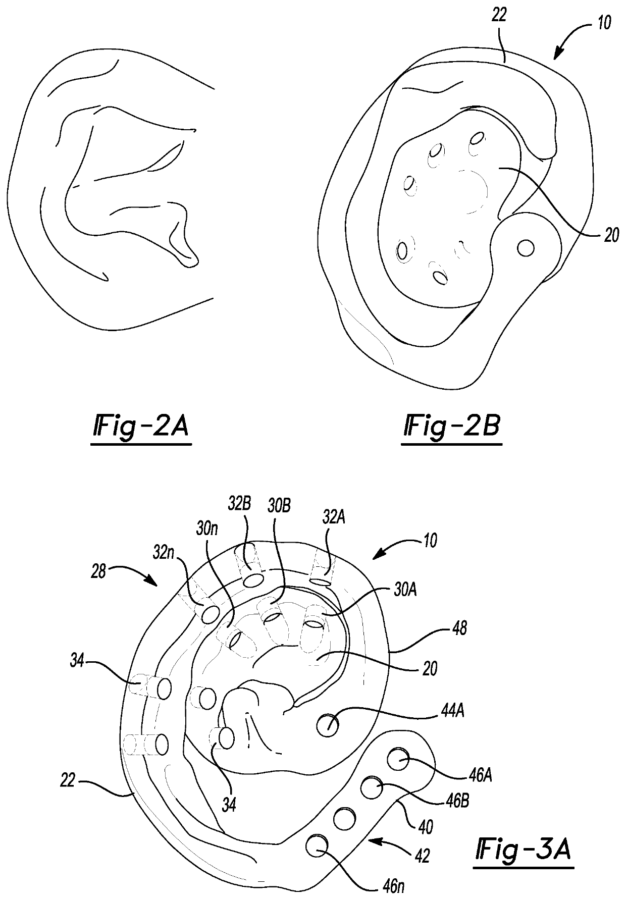
[0008]According to the principles of the present teachings, an ear splint to correct congenital ear deformities is provided that is both low-profile and comfortable. In some embodiments, the ear splint of the present teachings is particularly suitable for use on malleable infant ears. Ideally, the ear splint can be manufactured using a 3D printing technique to ensure proper configuration, comfort, and patient-specific fitment. This results in a patient-specific ear splint that is rapidly produced, at low-cost, and that avoids the need for skin adhesive that can lead to complications and skin breakdown.
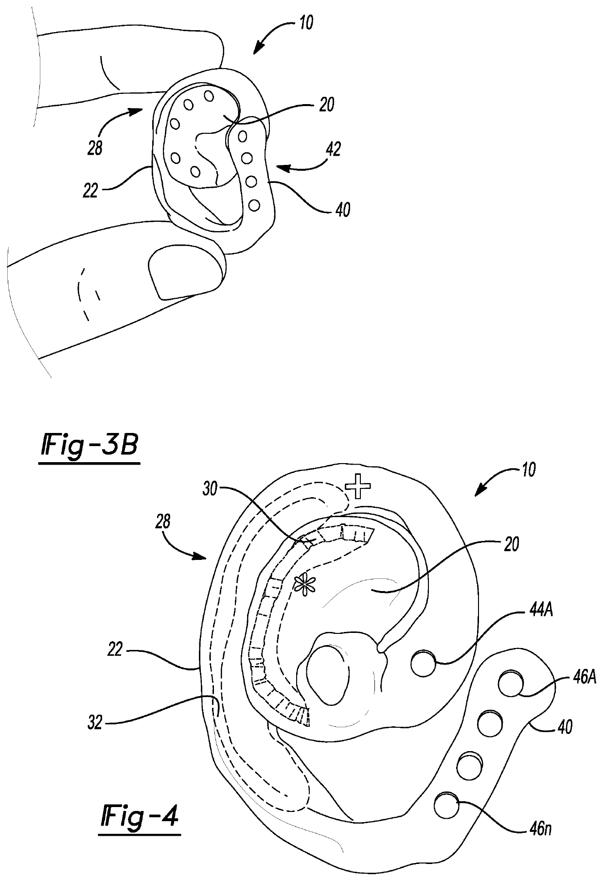
[0044]With the intended high level of ear feature specificity, circumferential ear design, and magnetic securement, fit is intended to be highly secure and comfortable. This design facilitates maintenance of placement making the device well suited for exercise and activity.

Problems solved by technology

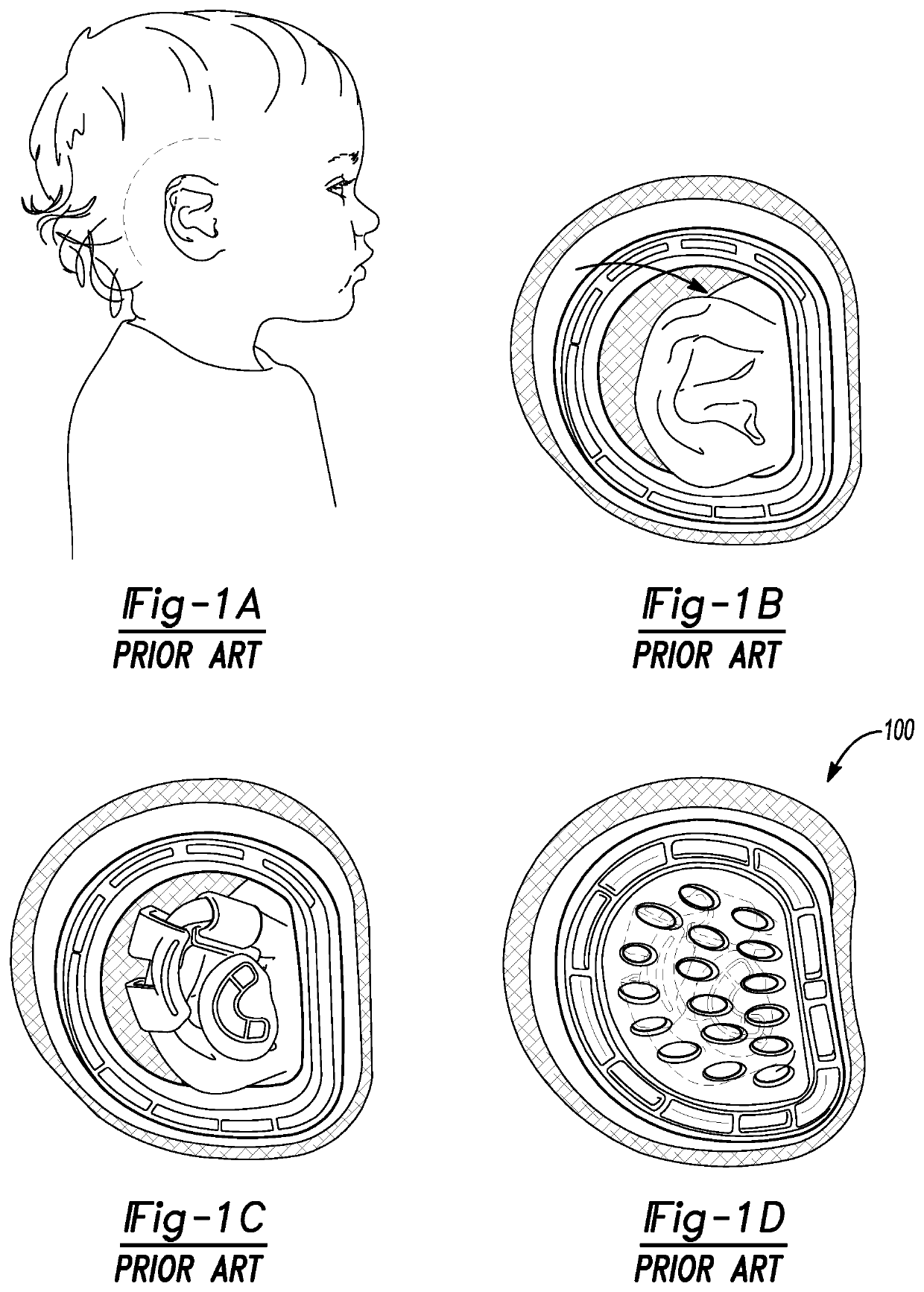
For children with ear deformities or malformations, there is dramatic psychosocial harm done to the child most often due to severe teasing and bullying.
Surgery is often costly, and the risks of anesthesia and other complications usually defer surgery until the child reaches at least six to ten years of age.
Unfortunately, surgical solutions after lead to outcomes that lack in both appearance and functionality.
Unfortunately, the device, due to its size and attachment method (i.e. adhesive), is susceptible to dislodgement and other complications.
Highly complex base and inserts prevents the possibility for replacement by the patient family.
The entire device is excessively large, poorly tolerated, and may be prone to displacement.

Method used


Image

  • Ear splint to correct congenital ear deformities
  • Ear splint to correct congenital ear deformities
  • Ear splint to correct congenital ear deformities

Examples


Embodiment Construction

[0023]Example embodiments will now be described more fully with reference to the accompanying drawings.

[0024]Example embodiments are provided so that this disclosure will be thorough, and will fully convey the scope to those who are skilled in the art. Numerous specific details are set forth such as examples of specific components, devices, and methods, to provide a thorough understanding of embodiments of the present disclosure. It will be apparent to those skilled in the art that specific details need not be employed, that example embodiments may be embodied in many different forms and that neither should be construed to limit the scope of the disclosure. In some example embodiments, well-known processes, well-known device structures, and well-known technologies are not described in detail.

[0025]The terminology used herein is for the purpose of describing particular example embodiments only and is not intended to be limiting. As used herein, the singular forms “a,”“an,” and “the” ...


PUM


Abstract

An ear splint for an ear is provided having a central portion having an exterior surface defining a first topology that is configured to dwell within an anterior scaphoid section of an ear, and a wing portion extending from the central portion and integrally formed therewith and at least partially surrounding an outer periphery of the central portion. The wing portion includes an exterior surface defining a second topology and is configured to be positioned along a postauricular area of the ear. The first magnetic device is disposed in the central portion and the second magnetic device is disposed in the wing portion. The magnetic retention feature exert a magnetic attractive force between the central portion and the wing portion such that at least a portion of the exterior surface of the central portion and at least a portion of the exterior surface of the wing portion contact the ear.

Description

CROSS-REFERENCE TO RELATED APPLICATIONS[0001]This application is a U.S. National Phase Application under 35 U.S.C. 371 of International Application No. PCT / US2017 / 051700 filed on Sep. 15, 2017. This application claims the benefit of U.S. Provisional Application No. 62 / 395,451, filed on Sep. 16, 2016. The entire disclosures of all of the above applications are incorporated herein by reference.FIELD[0002]The present disclosure relates to congenital ear deformities and, more particularly, to an ear splint to correct congenital ear deformities.BACKGROUND AND SUMMARY[0003]This section provides background information related to the present disclosure which is not necessarily prior art. This section also provides a general summary of the disclosure, and is not a comprehensive disclosure of its full scope or all of its features.[0004]It is well known that children can be born with ear malformations, which can often be the result of genetics, viral infections, and / or lack of blood supply or ...

Claims


Application Information

Patent Timeline
Patent Type & Authority Patents(United States)
IPC IPC(8): A61F5/01A61F5/058A61F11/20
CPCA61F11/202A61F5/0102A61F5/05891A61F2220/0025A61F11/00
Inventor ZOPF, DAVIDGREEN, KEVINVANKOEVERING, KYLE
Owner RGT UNIV OF MICHIGAN
Why Eureka
Try Eureka