Roof mesh installation apparatus

a technology for installing apparatuses and roofs, which is applied in shaft equipment, shaft linings, mining structures, etc., can solve the problems of reducing cross sectional area, limiting machine forward advancement rates and hence mining capacity, and prone to mesh sagging in existing mesh installation systems. to achieve the effect of enhancing mining capacity

Active Publication Date: 2022-05-24
SANDVIK INTELLECTUAL PROPERTY AB
View PDF38 Cites 0 Cited by
  • Summary
  • Abstract
  • Description
  • Claims
  • Application Information

AI Technical Summary

Benefits of technology

[0005]It is an objective of the present invention to provide a roof mesh installation apparatus for a mining machine capable of creating an effective rock support installation to suit particular rock types and situations. It is a further objective to provide supporting mesh installation apparatus offering variable machine forward advancement rates and enhanced mining capacity.
[0006]It is a further specific objective to provide mesh installation apparatus that may be conveniently integrated at a mining machine to provide an automatic or semi-automated system of roof support installation that maximises tunnel cross sectional area whilst minimising the risk of partial roof collapse or sagging during and post installation. It is a specific objective to provide an automated support installation apparatus offering flexibility of bolt spacing (in a lengthwise direction of the machine) and high capacity advancement rates to suit a variety of different rock types and situations as desired.
[0007]The objectives are achieved by providing a roof support installation system configured to apply a pre-tension to a mesh sheet as it is placed against the roof immediately prior to bolting in position. Applying a pre-tension to the mesh as it is unrolled automatically at the roof is advantageous to ensure the mesh is forced in a pre-tensioned state tight against the rock at the roof surface as the mesh is bolted in position. Variation of the magnitude of the pre-tension and the bolt spacing serves to maximise the strength of the rock support at the roof and achieve high machine advancement rates as required. In particular, the present system provides a fully automated or semi-automated arrangement of unrolling, pre-tensioning and bolting of mesh whilst the mining machine is advanced.

Problems solved by technology

However, existing mesh installation systems can be susceptible to mesh sagging both during and post installation.
Accordingly, any free-space between the mesh and roof is inevitably in-filled with rock and fines which reduces the cross sectional area of the as-created tunnel.
Additionally, existing arrangements are often restricted to single or predefined bolt spacing settings that in turn limit machine forward advancement rates and hence mining capacity.

Method used


Image

  • Roof mesh installation apparatus
  • Roof mesh installation apparatus
  • Roof mesh installation apparatus

Examples


Embodiment Construction

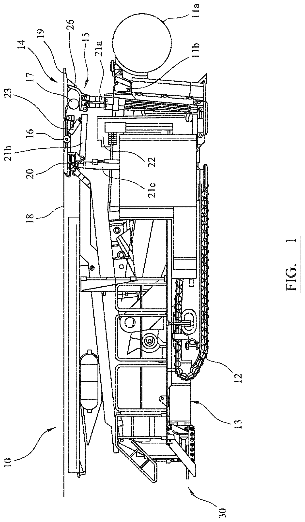
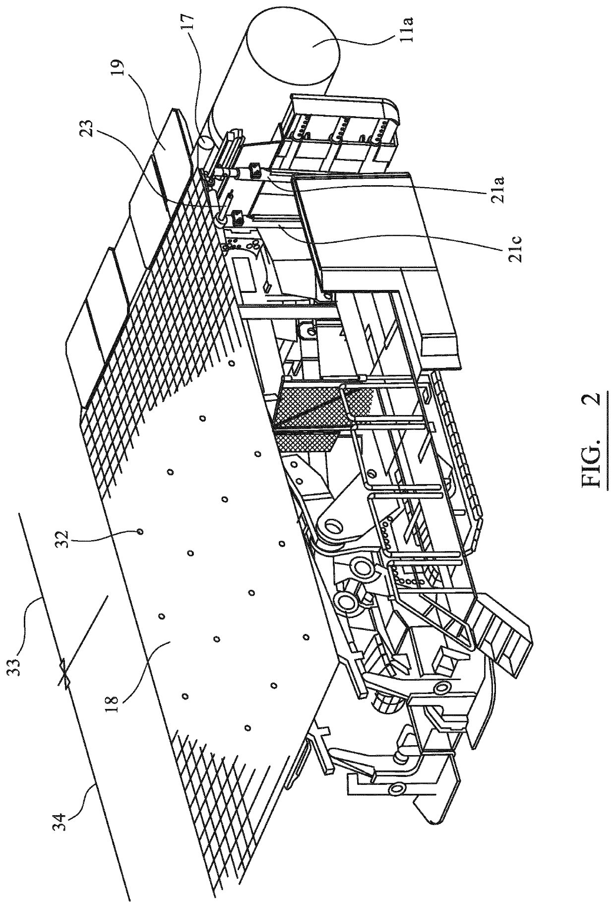
[0030]Referring to FIGS. 1 and 2, a mobile mining machine 10 comprises a pair of endless tracks 12 mounted at a chassis or mainframe 13 capable of moving the machine 10 over the ground or a floor of an underground tunnel and the like. A motor (not shown) is mounted at mainframe 13 and is configured to drive tracks 12 according to conventional machine arrangements. A rotatable cutting head 11a is mounted at a pivoting boom arm 11b and is capable of being raised and lowered to abrade the rock both as the machine 10 is advanced forward and cutting head 11a is raised and lowered.

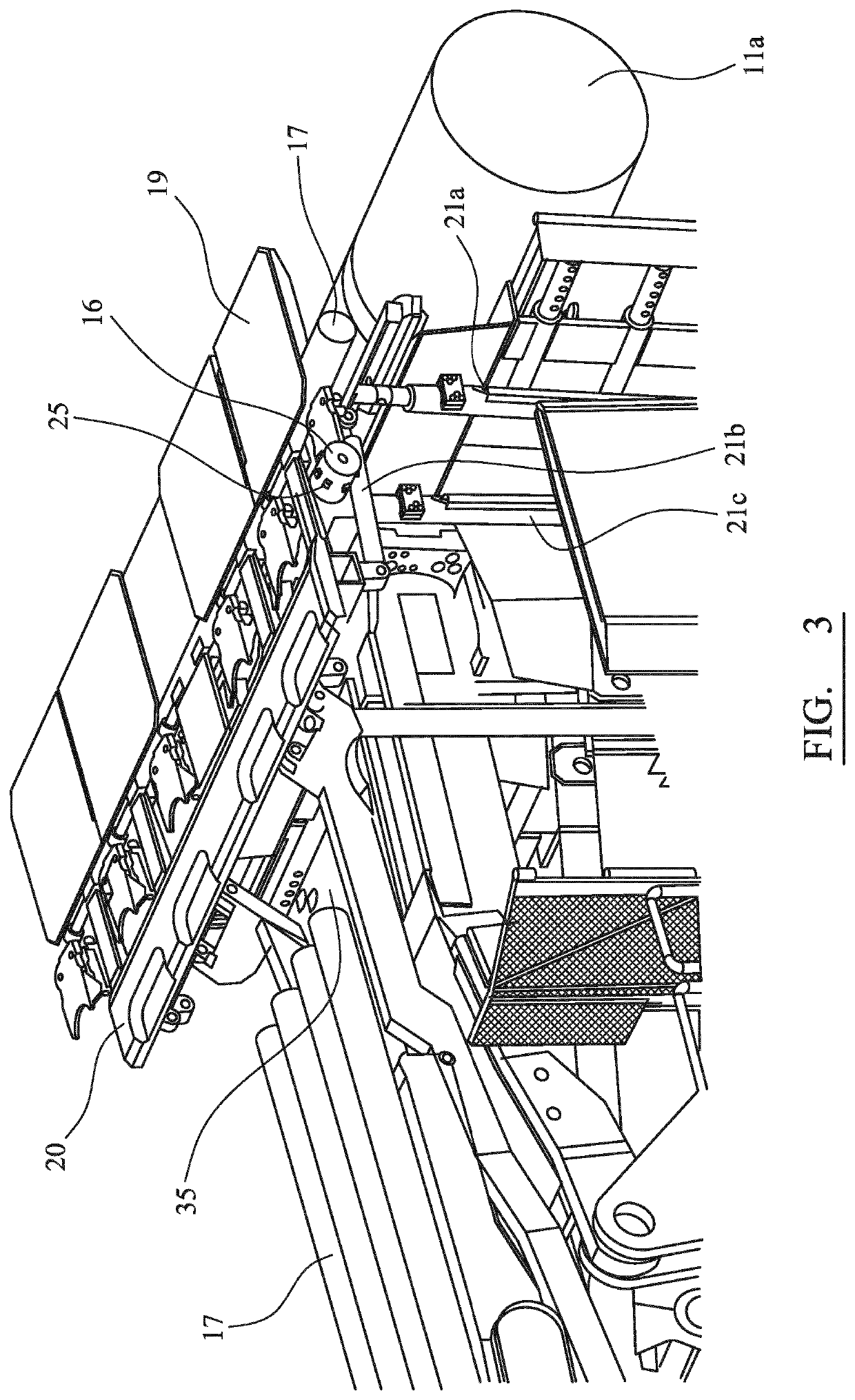
[0031]A roof mesh installation apparatus 14 is mounted at a forward end of machine 10 and is configured to provide both a temporary support to a roof section newly created by cutting head 11b and to provide a substantially permanent roof support in the form of a bolted mesh installed at the roof. Mesh installation apparatus 14 comprises a dispenser 15 that positionally supports a mesh roll 17 in close proximity ...


PUM


Abstract

A roof mesh installation apparatus for a mining machine includes a mesh roll carried at a dispenser at a forward position of the machine capable of unrolling mesh to be laid and bolted at a tunnel roof. A tensioning device positioned at the dispenser is capable of actuation so as to apply a pre-tension to a forward and unbolted section of mesh with the tension being applied against an already laid and rearward bolted mesh section. Accordingly, an automated roof mesh installation apparatus and method is provided.

Description

RELATED APPLICATION DATA[0001]This application is a § 371 National Stage Application of PCT International Application No. PCT / EP2017 / 064225 filed Jun. 12, 2017.FIELD OF INVENTION[0002]The present invention relates to a roof mesh installation apparatus for a mining machine and in particular, although not exclusively, to a system configured for the automated unrolling and pre-tensioning of a support mesh for securement against a roof structure.BACKGROUND ART[0003]Many different types of excavation and cutting machines have been developed to create drifts, tunnels, subterranean roadways and the like. For example, a mobile continuous mining machine is provided with crawler tracks to advance the machine forward, a pivoting boom mounting a rotatable cutting head to abrade into rock and a conveyor system to discharge rearwardly material cut from the rock face for subsequent rearward transportation.[0004]As will be appreciated, for reasons of safety and forward cutting efficiency, it is imp...

Claims


Application Information

Patent Timeline
Patent Type & Authority Patents(United States)
IPC IPC(8): E21D11/40E21D11/15
CPCE21D11/152E21D11/406E21D11/40
Inventor GALLER, THOMASREUMULLER, BRUNO
Owner SANDVIK INTELLECTUAL PROPERTY AB
Why Eureka
Try Eureka