
Multi-carrier receiver with improved radio frequency interference canceling

a receiver and carrier technology, applied in the field of multi-carrier receivers, can solve the problem of lower maximum achievable capacity, and achieve the effect of increasing the minimum guaranteed capacity

Inactive Publication Date: 2005-07-12
RPX CORP
View PDF6 Cites 2 Cited by
  • Summary
  • Abstract
  • Description
  • Claims
  • Application Information

AI Technical Summary

Benefits of technology

[0005]An object of the present invention is to provide multi-carrier receiver similar to the known one, but which is able to estimate the characteristics of a narrowband disturber in the standardised RFI band accurately, irrespective of the location of this narrowband disturber in the RFI band, and whose minimum guaranteed capacity is increased.
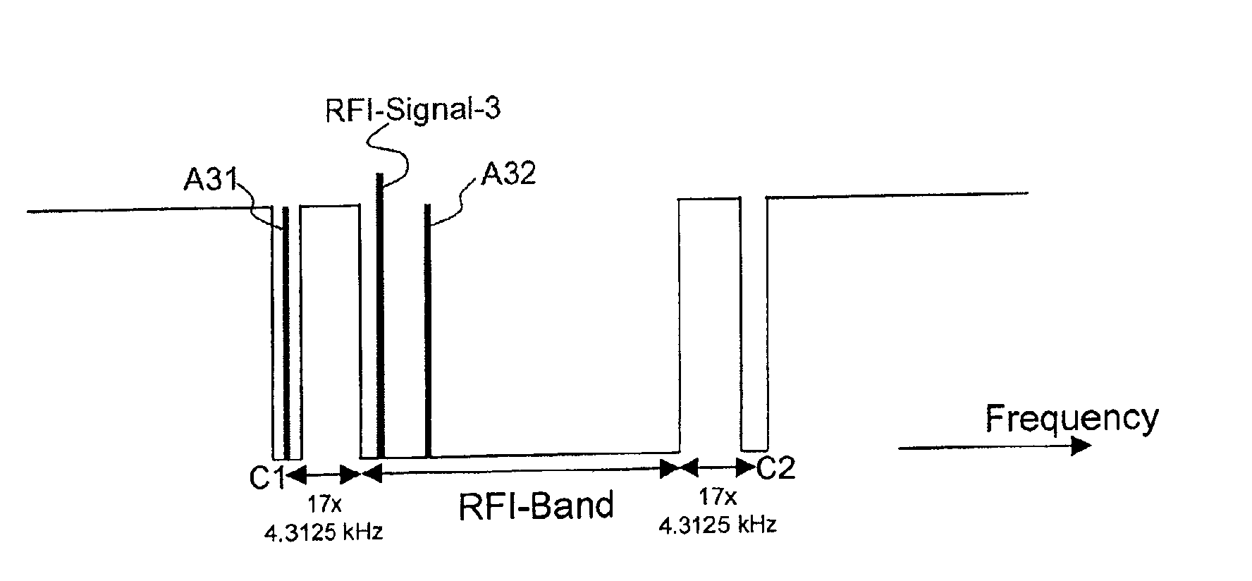
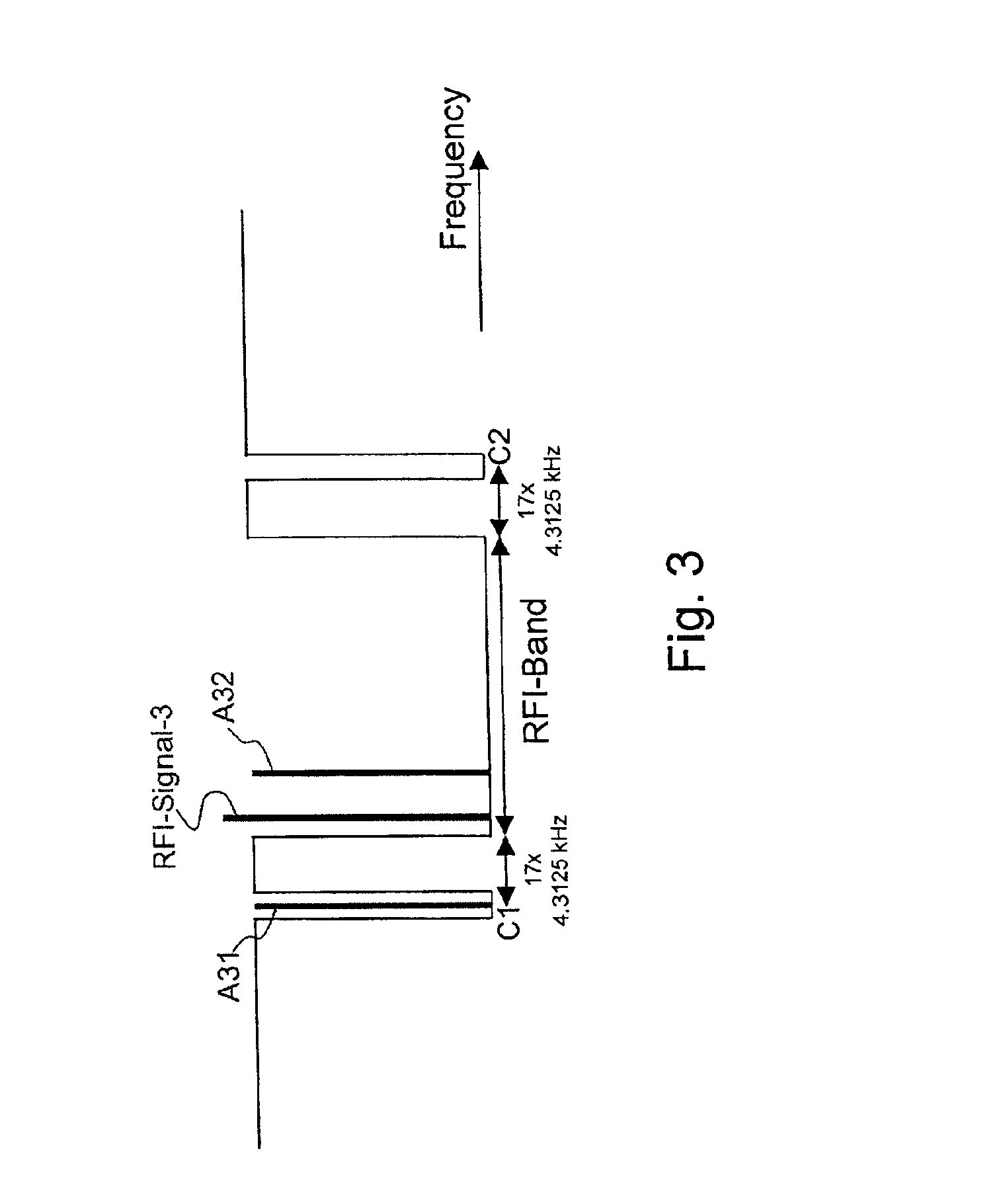
[0006]Indeed, the antennas no longer have to be chosen exclusively within the RFI band, but alternatively may be chosen amongst the carriers in the RFI band and at least two carriers located outside the RFI band. In case the narrowband interferer is not optimally located, i.e. near to an edge of the RFI band, one antenna can be selected inside the RFI band and a second antenna can be chosen outside the RFI band so that the two antennas are located at opposite sides of the narrowband disturber and at sufficient distance thereof in order to allow an accurate estimation of the characteristics of the narrowband disturber. Since the characteristics of a narrowband disturber in the worst case situation where this narrowband disturber is located at an edge of the RFI band can be estimated more accurately according to the present invention, the effects of the worst case narrowband disturber can be compensated for more optimally resulting in an increased minimum guaranteed capacity.

Problems solved by technology

A minor disadvantage of the multi-carrier receiver according to the present invention is that its maximum achievable capacity is lower than that of the known DMT receiver because at least two carriers outside the RFI band are set to zero (no or small amount of power and data bits allocated thereto).

Method used


Image

  • Multi-carrier receiver with improved radio frequency interference canceling
  • Multi-carrier receiver with improved radio frequency interference canceling
  • Multi-carrier receiver with improved radio frequency interference canceling

Examples


Embodiment Construction

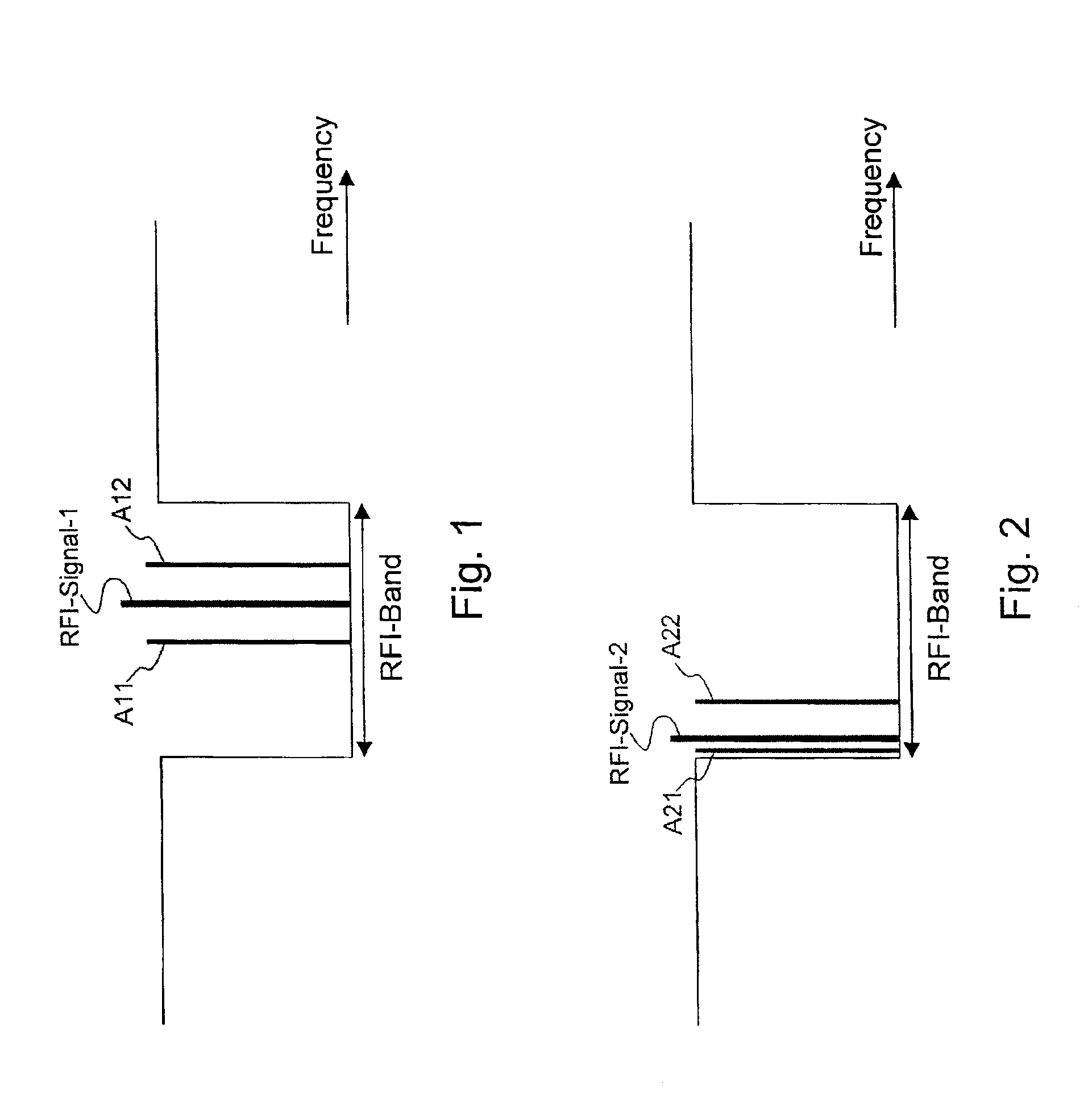
[0016]FIG. 1 illustrates the operation of a prior art multi-carrier receiver. The receiver receives a multi-carrier signal containing for instance 1024 carriers modulated with digital data. The interspacing between two carriers equals 4.3125 kHz. Part of the carriers have frequencies inside the Radio Frequency Interference band, RFI-Band in FIG. 1. This RFI-Band is a predetermined, standardised frequency interval reserved for e.g. radio amateur transmission. To avoid disturbance of the radio amateur emission in the RFI-Band, the power spectral density of the multi-carrier signal within this RFI-Band should be −80 dB / Hz or −60 dB / Hz. This is drawn in FIG. 1, and implies that only a very limited amount of power and data bits can be allocated to the carriers having frequencies within this RFI-Band. The prior art multi-carrier receiver contains circuitry and software to roughly determine the location of a narrowband disturber RFI-Signal-1, e.g. a radio amateur signal, in the RFI-Band. T...


PUM


Abstract

A multi-carrier receiver selects antennas (A31, A32), i.e. carriers whereto a small amount of power and data is allocated, for estimation of characteristics of a narrowband disturber (RFI-Signal-3) in the Radio Frequency Interference band (RFI-Band), a predetermined band for e.g. radio amateur transmission. These antennas (A31, A32) can be selected amongst all carriers located inside the Radio Frequency Interference band (RFI-Band) and at least two carriers (C1, C2) located outside the Radio Frequency Interference band (RFI-Band).

Description

BACKGROUND OF THE INVENTION[0001]The present invention relates to a multi-carrier receiver.[0002]Such a multi-carrier receiver is already known in the art, e.g. from the article ‘Mitigation of radio Interference in xDSL Transmission’ from the authors Luc de Clercq, Miguel Peeters, Sigurd Schelstraete and Thierry Pollet. This article has been published in IEEE Communications Magazine, March 2000, pag. 168-173. The DMT (Discrete Multi Tone) receiver drawn in FIG. 3 of this article and described on page 172 in the paragraph entitled ‘Digital RFI Canceling’ receives a multi-carrier DMT signal and demodulates digital data contained in DMT symbols from the set of carriers constituting the multi-carrier DMT signal. In order not to disturb radio amateur transmission, the PSD (Power Spectral Density) of the multi-carrier DMT signal stays below a certain maximum value within predetermined, standardised frequency bands: the so called RFI (Radio Frequency Interference) bands listed in table 1 o...

Claims


Application Information

Patent Timeline
Patent Type & Authority Patents(United States)
IPC IPC(8): H04L27/26H04B1/10
CPCH04B1/1036H04L27/2602H04L27/2647
Inventor ANTOINE, PHILIPPEPOLLET, THIERRY
Owner RPX CORP
Learn More