
Cell structure of solid state battery

a solid-state battery and cell structure technology, applied in the field of cell structure of solid-state batteries, can solve the problems of heat-related safety particularly becoming an issue, durability issue, and inability to uniformly dispose of shock absorbers in the battery cas

Active Publication Date: 2022-05-24
HONDA MOTOR CO LTD
View PDF16 Cites 0 Cited by
  • Summary
  • Abstract
  • Description
  • Claims
  • Application Information

AI Technical Summary

Benefits of technology

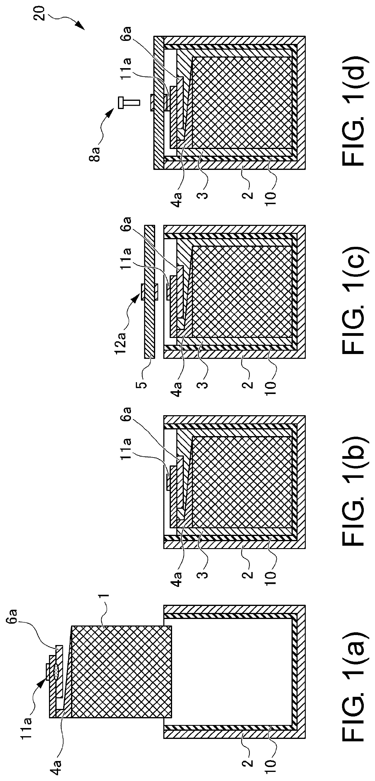
[0038]In addition, in the manufacturing method of the solid state battery of the disclosure, in order to provide sufficient airtightness to the obtained solid state battery, the structure of the terminal engaging member to which the terminal is connected may be configured as a structure such as a threaded nut, the terminal is configured as a structure such as a bolt, and these structures are engaged to be fastened in the terminal fastening process. The cell structure of the solid state battery according to an exemplary embodiment will be described in the following.

Problems solved by technology

Since the electrolytic solution of the lithium ion secondary battery is usually a flammable organic solvent, there have been cases in which heat-related safety has particularly become an issue.
As a result, a configuration in which the solid state battery cell is not held in the battery case is formed, and a durability issue, such as cracking during vibration, may arise.
Nevertheless, in this technique, it is anticipated that the shock absorber is not uniformly disposed in the battery case, and it is difficult to uniformly hold the solid state battery cell in the case.
In addition, in the case where a curable resin is used as the shock absorber, there is a concern that the stress at the time of curing may be applied to the solid state battery cell and a crack may occur.
However, in the case where the lid is provided to finish up the can cell after the shock absorber is inserted, an airtightness issue of the obtained can cell may arise.

Method used


Image

  • Cell structure of solid state battery
  • Cell structure of solid state battery
  • Cell structure of solid state battery

Examples


first embodiment

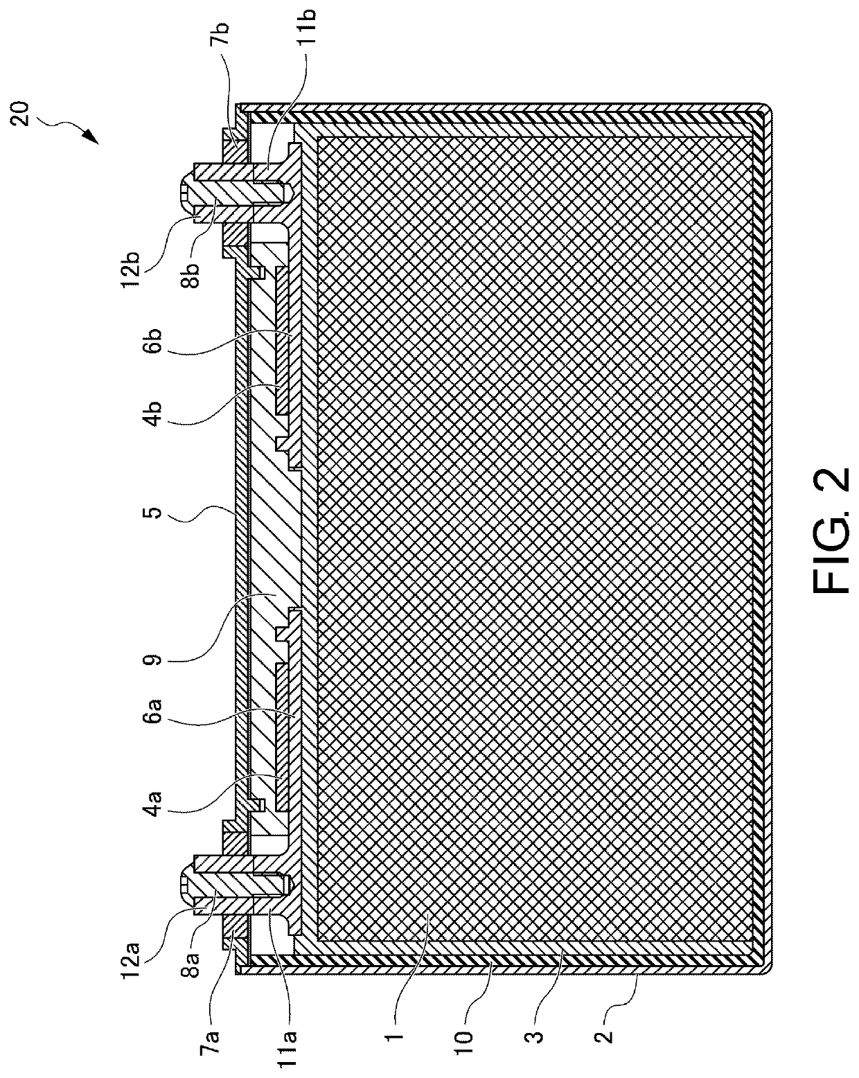
[0042]FIG. 2 shows the cell structure of the solid state battery of the disclosure according to the first embodiment. In the cell structure of the solid state battery 20 shown in FIG. 2, the solid state battery cell 1 is stored in the storage body 2 of the battery case in which the insulating sheet 10 is installed, and the shock absorber 3 is disposed in the clearance between the solid state battery cell 1 and the storage body 2 of the battery case.

[0043]In addition, the positive electrode power collecting member 6a and a negative electrode power collecting member 6b are respectively connected to the positive electrode tab 4a and a negative electrode tab 4b extending from the solid state battery cell 1, and the positive electrode power collecting member 6a and the negative electrode power collecting member 6b include the positive electrode terminal engaging member lower end part 11a and a negative electrode terminal engaging member lower end part 11b. Moreover, a power collecting me...

second embodiment

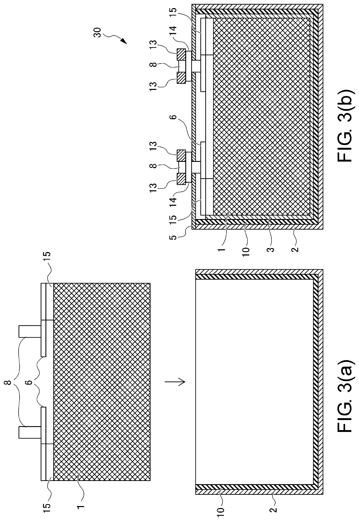
[0069]The cell structure of the solid state battery of the disclosure according to the second embodiment will be described with reference to FIGS. 3(a) and 3(b). FIG. 3(a) is a view showing the solid state battery cell storing process in which the solid state battery cell 1 is stored in the storage body 2 of the battery case in which the insulating sheet 10 is installed. FIG. 3(b) is a view showing the cell structure of a solid state battery 30 according to the second embodiment.

[0070]In the cell structure of the solid state battery 30 shown in FIG. 3(b), the solid state battery cell 1 is stored in the storage body 2 of the battery case in which the insulating sheet 10 is installed, and the shock absorber 3 is disposed in the clearance between the solid state battery cell 1 and the storage body 2 of the battery case.

[0071]In addition, tabs 15 of the positive electrode and the negative electrode extending from the solid state battery cell 1 are respectively connected with the power c...


PUM

PropertyMeasurementUnit
cell structureaaaaaaaaaa
energy densityaaaaaaaaaa
durabilityaaaaaaaaaa

Abstract

The disclosure provides a cell structure of a solid state battery capable of uniformly holding a solid state battery cell in a battery case and a manufacturing method of a solid state battery. In a process of manufacturing a can cell of the solid state battery, a shock absorber is disposed in the battery case after the solid state battery cell is inserted into the battery case and before a can lid is welded. Then, the lid is provided to seal the case. At the time of sealing, the solid state cell and a terminal are fastened by using an engaging member, and the airtightness is improved.

Description

CROSS-REFERENCE TO RELATED APPLICATION[0001]This application claims the priority benefit of Japan application no. 2018-241369, filed on Dec. 25, 2018. The entirety of the above-mentioned patent application is hereby incorporated by reference herein and made a part of this specification.BACKGROUNDTechnical Field[0002]The disclosure relates to a cell structure of a solid state battery and a manufacturing method of a solid state battery. Specifically, the disclosure relates to a cell structure of a solid state battery capable of uniformly holding a solid state battery cell in a battery case and a manufacturing method of a solid state battery.Description of Related Art[0003]Conventionally, as secondary batteries having high energy density, lithium ion secondary batteries are extensively used. A lithium ion secondary battery has a structure in which a separator is present between a positive electrode and a negative electrode and liquid electrolyte (electrolytic solution) is filled therei...

Claims


Application Information

Patent Timeline
Patent Type & Authority Patents(United States)
IPC IPC(8): H01M50/186H01M50/191H01M50/531H01M50/543H01M50/183H01M50/188H01M50/567H01M50/55H01M10/058H01M50/148H01M50/553H01M50/15
CPCH01M50/186H01M10/058H01M50/148H01M50/183H01M50/188H01M50/191H01M50/531H01M50/543H01M50/55H01M50/553H01M50/567H01M50/15
Inventor TANIUCHI, TAKUYAOHTA, MASAHIROASAHI, YURIKO
Owner HONDA MOTOR CO LTD
Learn More