User equipment (UE) transmitter and base station receiver for transmissions from a UE to a base station

a technology of user equipment and transmission, applied in the field of wireless communication systems, can solve the problems of affecting the performance of both downlink and uplink, affecting the performance of transmission from the base station, and affecting the performance of transmission from the u

Active Publication Date: 2022-05-31
QUALCOMM INC
View PDF1 Cites 0 Cited by
  • Summary
  • Abstract
  • Description
  • Claims
  • Application Information

AI Technical Summary

Problems solved by technology

On the downlink, a transmission from the base station may encounter interference due to transmissions from neighbor base stations or from other wireless radio frequency (RF) transmitters.
On the uplink, a transmission from the UE may encounter interference from uplink transmissions of other UEs communicating with the neighbor base stations or from other wireless RF transmitters.
This interference may degrade performance on both the downlink and uplink.

Method used


Image

  • User equipment (UE) transmitter and base station receiver for transmissions from a UE to a base station
  • User equipment (UE) transmitter and base station receiver for transmissions from a UE to a base station
  • User equipment (UE) transmitter and base station receiver for transmissions from a UE to a base station

Examples


Embodiment Construction

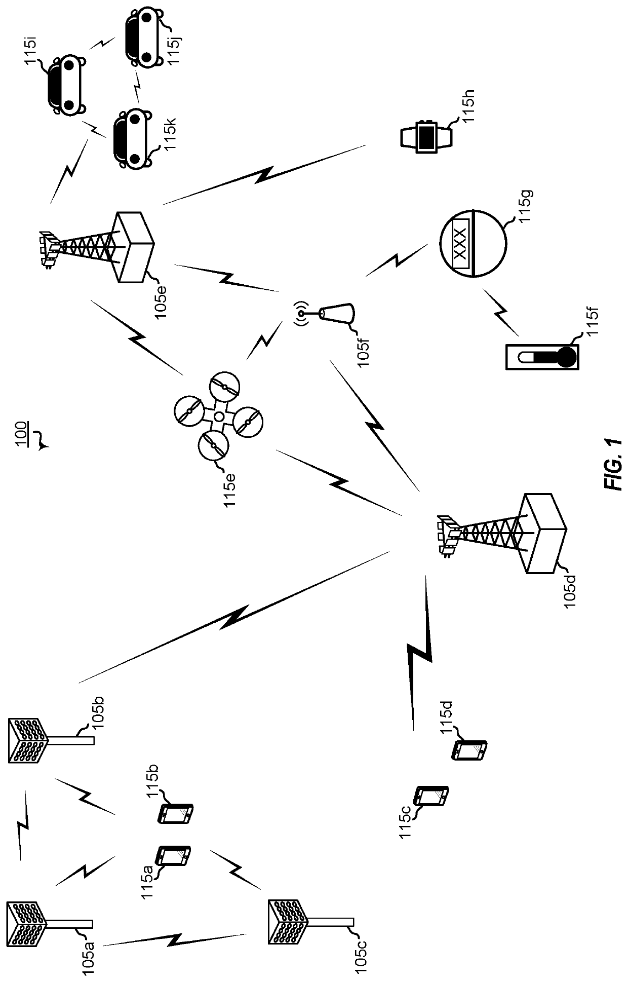
[0030]Wireless signals sent within a wireless communication system may be subject to noise, interference, and other conditions that reduce signal quality. To compensate for effects of noise, interference, and other conditions, some wireless communication systems use reference signals to estimate and then reduce or cancel the effects. For example, a user equipment (UE) may send a demodulation reference signal (DMRS) to a base station, and the base station may use the DMRS to estimate and compensate for effects of noise, interference, and other conditions on other signals sent by the UE to the base station. Transmission of signals using the DMRS may be referred to as a coherent transmission technique.

[0031]In some cases, DMRS-based communications may be less efficient than another technique, such as a non-coherent transmission technique. For example, in some circumstances, use of a DMRS may provide a poor estimate of the effects of noise, interference, and other conditions, such as in...


PUM


Abstract

An apparatus for wireless communication includes a receiver configured to receive control information associated with a non-coherent transmission to a base station. The apparatus further includes a transmitter configured to perform the non-coherent transmission based on the control information. The non-coherent transmission includes transmission of a codepoint to the base station, and the codepoint is determined based a diagonalized base sequence parameter matrix, a first discrete Fourier transform (DFT) matrix of a first size, and a second DFT matrix of a second size.

Description

CROSS-REFERENCE TO RELATED APPLICATIONS[0001]This application claims the benefit of and priority to U.S. Prov. Pat. App. No. 63 / 028,359, entitled, “BASE STATION RECEIVER FOR TRANSMISSIONS FROM A USER EQUIPMENT,” filed on May 21, 2020, which is expressly incorporated by reference herein in its entirety.TECHNICAL FIELD[0002]Aspects of the present disclosure relate generally to wireless communication systems, and more particularly, to transmitters and receivers for wireless communication systems.INTRODUCTION[0003]Wireless communication networks are widely deployed to provide various communication services such as voice, video, packet data, messaging, broadcast, and the like. These wireless networks may be multiple-access networks capable of supporting multiple users by sharing the available network resources. Such networks, which are usually multiple access networks, support communications for multiple users by sharing the available network resources.[0004]A wireless communication netw...

Claims


Application Information

Patent Timeline
Patent Type & Authority Patents(United States)
IPC IPC(8): H04L27/26
CPCH04L27/26524H04L27/2634H04L27/2636H04L27/26526H04L27/26025
Inventor ELSHAFIE, AHMEDHUANG, YIKWON, HWAN JOON
Owner QUALCOMM INC
Why Eureka
Try Eureka