
Ligature resistant floor drain and grate

a technology of ligature and floor drain, which is applied in the direction of water installations, sewer systems, construction, etc., can solve the problem of not being able to completely eliminate the possibility of a patien

Active Publication Date: 2022-06-14
ACORN ENG
View PDF10 Cites 2 Cited by
  • Summary
  • Abstract
  • Description
  • Claims
  • Application Information

AI Technical Summary

Benefits of technology

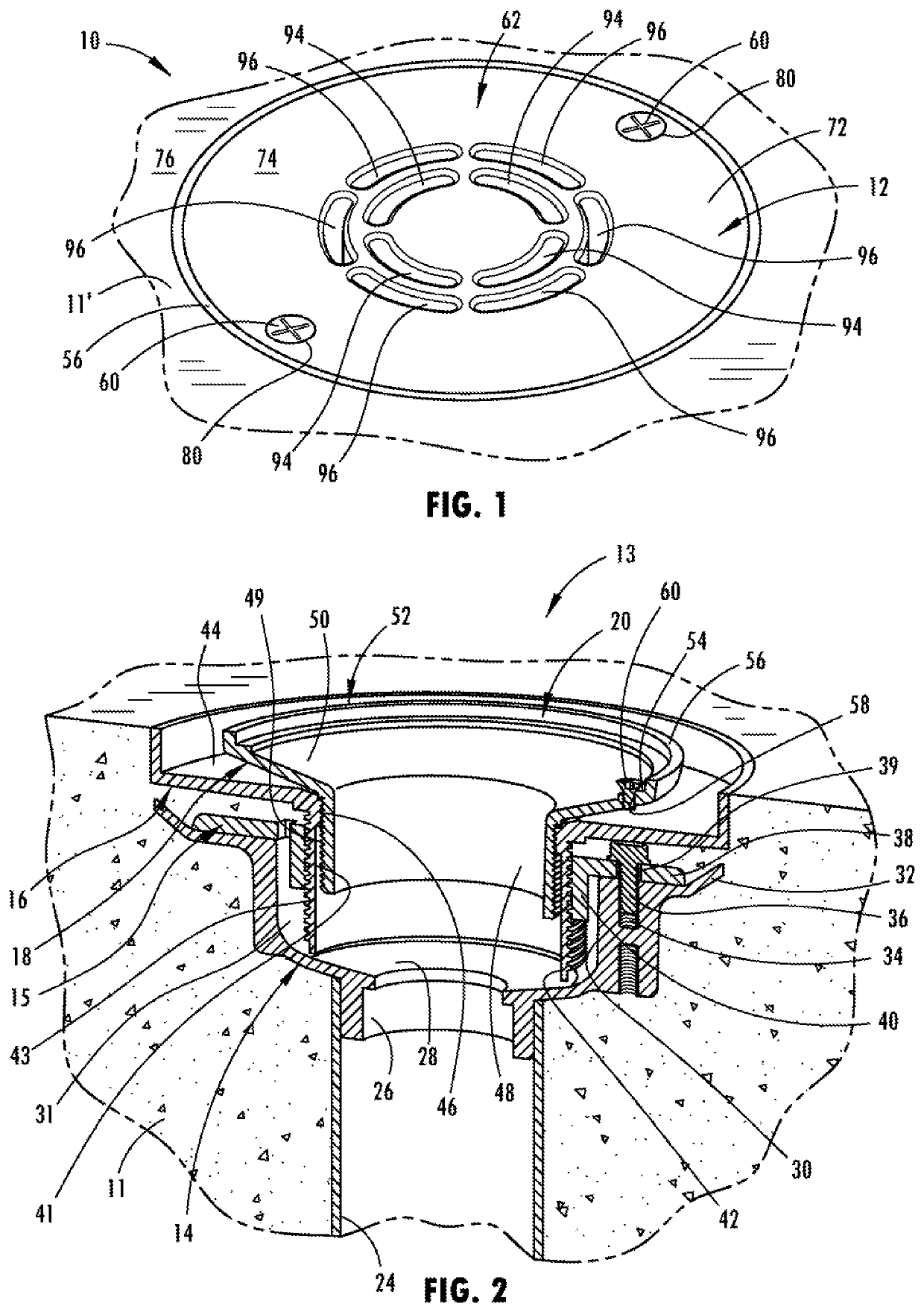
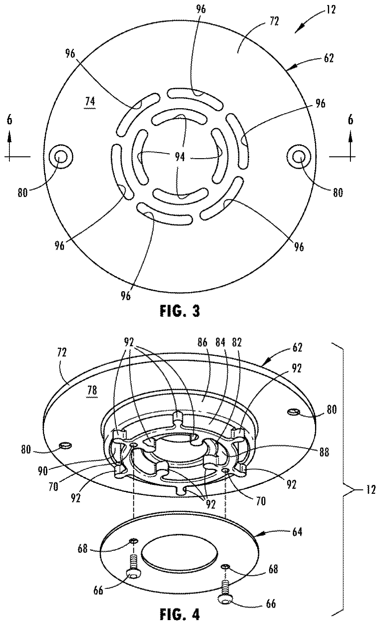
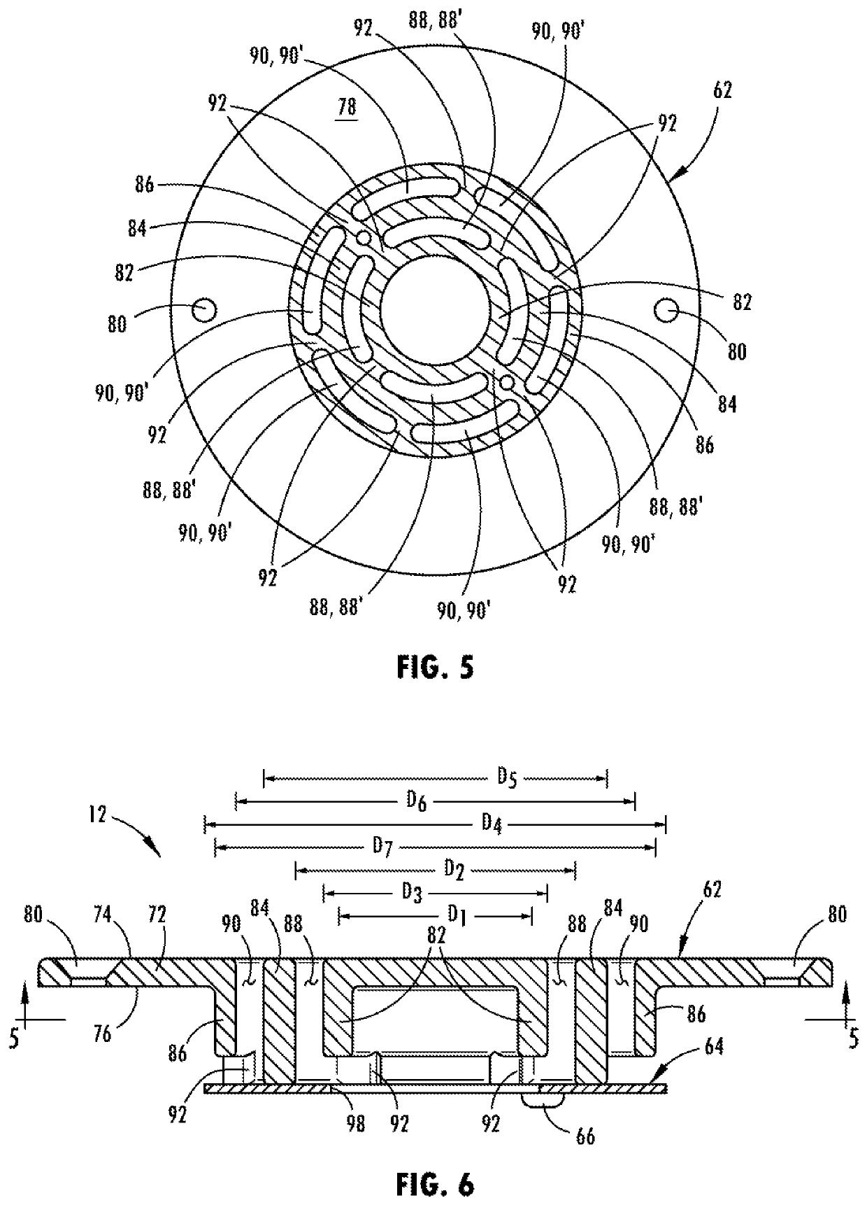
The present invention provides a strainer for a ligature resistant floor drain that includes a top plate with multiple openings. The openings are organized into two sets of rings, with the inner ring located inside the outer ring. A cylindrical extension is connected between the top plate and the openings, and a plurality of inner and outer webs are connected to the cylindrical extension to separate the openings. The strainer is mounted to a strainer frame that includes an outlet in fluid communication with both sets of openings. The technical effects of the invention include improved resistance to ligature and floor drain blockages, as well as improved strainer performance and ease of installation.

Problems solved by technology

While it may be impossible to completely eliminate the possibility of a patient suicide using a ligature, mental health and other institutions are desirous of incorporating structures within their facilities that discourage the formation of a ligature point.

Method used


Image

  • Ligature resistant floor drain and grate
  • Ligature resistant floor drain and grate
  • Ligature resistant floor drain and grate

Examples


Embodiment Construction

[0039]As used in the description that follows, directional terms such as “upper” and “lower” are used with reference to the orientation of the features and elements of the floor drain, as represented by the installed position and as generally shown in the figures. Accordingly, “upper” indicates a direction toward the top of the figure or toward the exposed portion of the installed floor drain and “lower” indicates a direction toward the bottom of the figure or toward the non-exposed portions of the of the figure. The terms “inward” or “inner” and “outward” or “outer” indicate a direction that is generally toward or away from a central axis of the floor drain, whether or not such an axis is designated in the referred to figure. An axial surface is one that faces in the axial direction. In other words, an axial surface faces in a direction generally along the central axis. A radial surface therefore faces radially, generally away from or toward the central axis.

[0040]Referring now to ...


PUM


Abstract

A strainer for a ligature resistant floor drain and a ligature resistant floor drain incorporating a strainer. The strainer includes a top plate with two sets of openings forming rings. A cylindrical extension extends from the top plate at a location between the rings. Also provided are two series of webs, each web of which is located between an adjacent pair of openings in one of the rings. Optionally, a strainer plate is attached to the cylindrical extension and extends at least one of radially inward and outward relative from the cylindrical extension. The floor drain further includes a strainer frame having a receptacle into which the strainer is received.

Description

BACKGROUND1. Field of the Invention[0001]The present invention generally relates to floor drains, such as a floor drain intended to be installed in a concrete floor. More specifically, the invention relates to a floor drain, and a grate for a floor drain, that is resistant to the attachment of a ligature device.2. Description of Related Art[0002]Floor drains are installed in buildings so that liquid, usually water, received on the floor is quickly and easily drained off of the floor, preventing both people from slipping on the floor and damage to the floor or other structural aspects of the installation site. Since the floor drain of the present type are typically installed in poured concrete floors, the floor drain are precisely located and aligned with the finished grade so as to ensure proper operation of the floor drain and to not pose a tripping hazard. Floor drains of this variety are found in numerous types of installation sites including, without limitation, the kitchens, re...

Claims


Application Information

Patent Timeline
Patent Type & Authority Patents(United States)
IPC IPC(8): E03F5/06E03F5/04E03C1/26
CPCE03F5/06E03C1/26E03F5/0407E03F5/04
Inventor BOELTL, DARRYL M.
Owner ACORN ENG
Learn More