Projector stand

Active Publication Date: 2022-07-05
IZUMI COSMO CO
View PDF13 Cites 0 Cited by
  • Summary
  • Abstract
  • Description
  • Claims
  • Application Information

AI Technical Summary

Benefits of technology

The patent describes a projector stand that can be easily attached and detached from a projected body, making it easy to move around. The height of the projector can also be adjusted to match the height of the projected body, making it more versatile and user-friendly. The technical effect is that this makes it more convenient and efficient to use the projector in different situations.

Problems solved by technology

Incidentally, since the stand disclosed in Patent Document 1 is attached to an edge of a table by using a clamping mechanism, there has been a problem that the work associated with attaching and detaching the stand to and from the table is cumbersome.

Method used


Image

  • Projector stand
  • Projector stand
  • Projector stand

Examples


Embodiment Construction

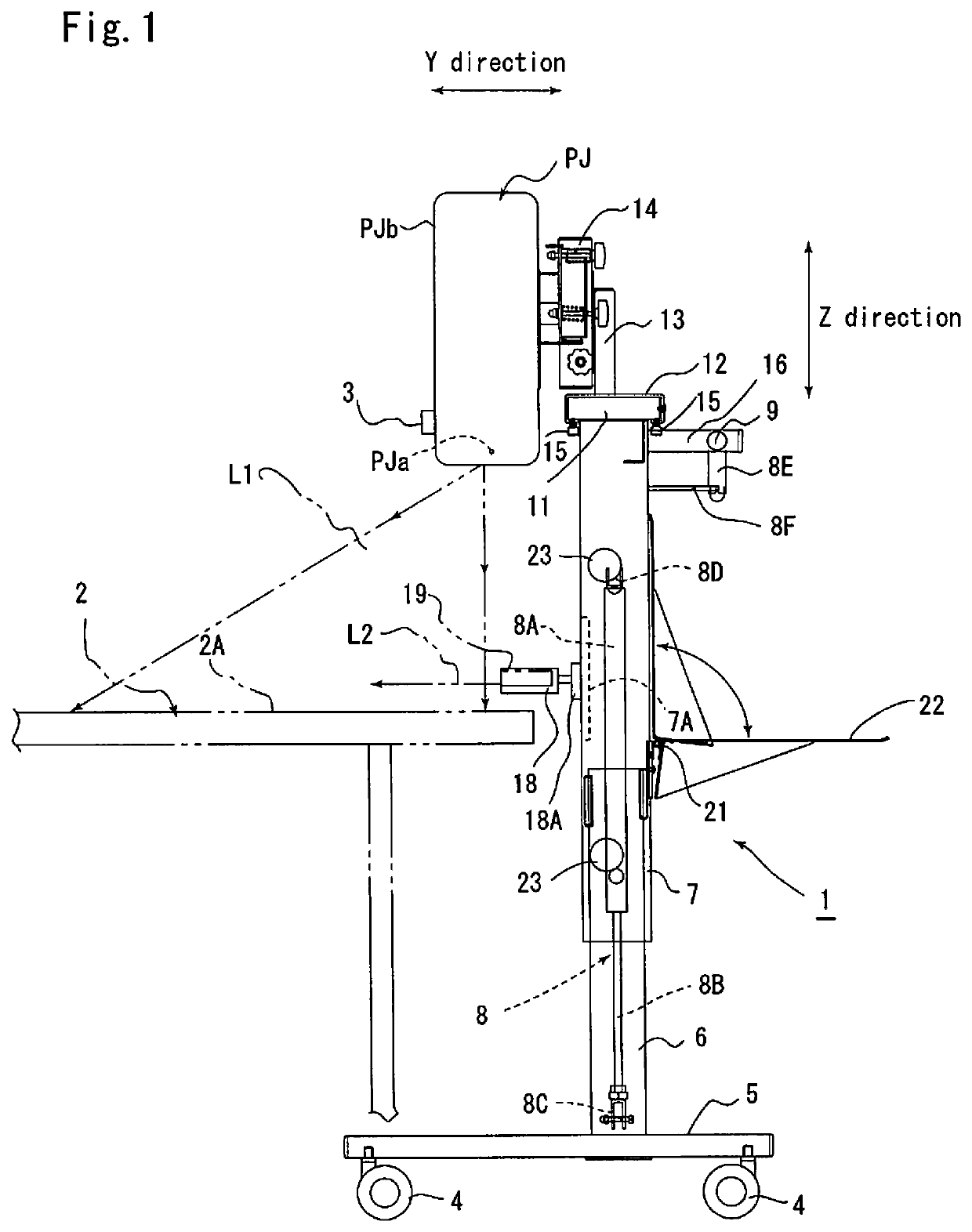
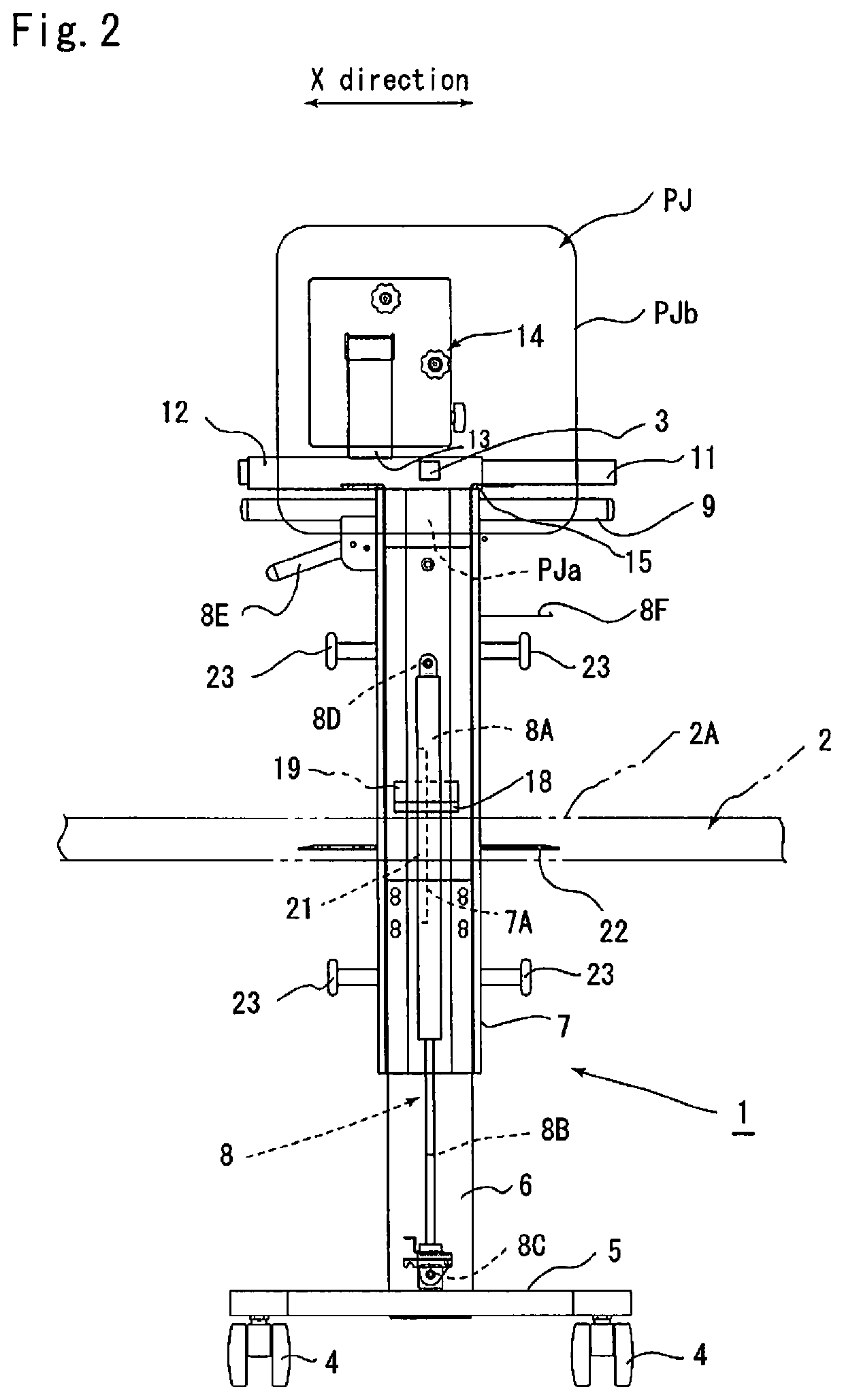
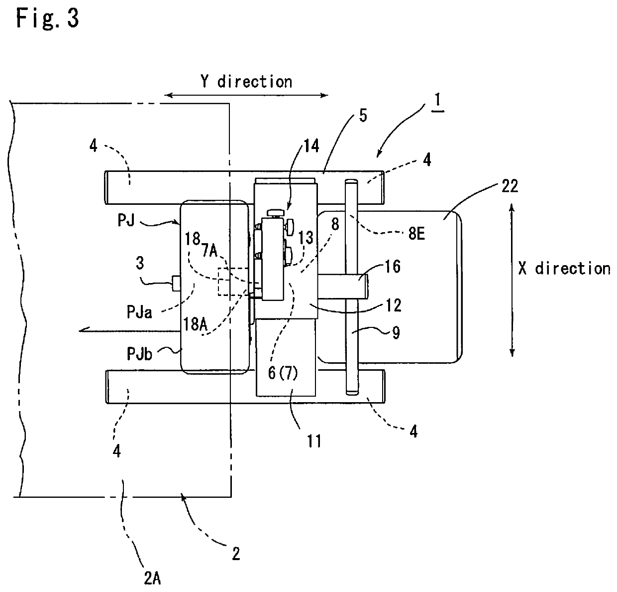
[0010]Hereinafter, the present invention will be described with reference to an example shown in the drawings. In FIGS. 1 to 3, reference numeral 1 denotes a projector stand, the projector stand 1 supporting an ultra-short throw projector PJ and movable to a desired position.

[0011]The configuration of the ultra-short throw projector PJ has conventionally been known. By projecting projection light L1 downward toward a top board 2A of a table 2 from a projection lens PJa of the ultra-short throw projector PJ, an image can be projected on the top board 2A of the table 2. In the example, it is assumed that the projected body is the table 2, and the flat top board 2A of the table 2 is a projection surface on which an image is projected.

[0012]The ultra-short throw projector PJ includes a box-shaped casing PJb, and a sensor 3 is attached to a predetermined position on a front surface of the casing PJb so as to face the top board 2A of the table 2. When an operator moves a pen on the top bo...


PUM


Abstract

A projector stand includes an elevator member fitted to a strut such that the elevator member can be raised and lowered, a guide plate fixed to the upper end of the elevator member, a slide member horizontally movable along the guide plate, and a three-axis adjustment mechanism provided or the slide member.

Description

TECHNICAL FIELD[0001]The present invention relates to a projector stand, and more specifically to a movable projector stand suitable for an ultra-short throw projector.BACKGROUND ART[0002]Heretofore, a stand that supports a projector capable of projecting an image toward a top board of a table from above has been known (Patent Document 1).PRIOR ART DOCUMENTPatent Document 1[0003]Japanese Laid-Open Patent Application No. 2007-193120SUMMARY OF THE INVENTION[0004]Incidentally, since the stand disclosed in Patent Document 1 is attached to an edge of a table by using a clamping mechanism, there has been a problem that the work associated with attaching and detaching the stand to and from the table is cumbersome.[0005]In view of the foregoing, the present invention provides a projector stand supporting an ultra-short throw projector that projects an image downward toward a projection surface of a projected body from above, the projector stand being characterized by including: a movable ba...

Claims


Application Information

Patent Timeline
IPC IPC(8): G03B21/10F16M11/10F16M11/20F16M11/24F16M11/42F16M11/02F16M11/12F16M11/04A47B97/00G03B21/54
CPCG03B21/10F16M11/2092F16M11/24F16M11/42A47B97/00F16M11/02F16M11/046F16M11/12G03B21/54H04N5/74G03B21/145F16M11/18F16M11/048F16M11/2085F16M11/28
Inventor SEKI, KAZUHARUKAMEDA, SHUHEIABE, TERUYUKI
Owner IZUMI COSMO CO
Why Eureka
Try Eureka