Maintenance device and method for determining the position of a blockage point of a tubular member

a technology of a maintenance device and a position determination device, which is applied in the direction of surveying, wellbore/well accessories, constructions, etc., can solve the problems of putting at risk the safety of operators and stability, affecting the operation of drilling operations, and difficult, if not impossible, to clear one or more blocked sections

Active Publication Date: 2022-07-12
FEBUS OPTICS +1
View PDF23 Cites 0 Cited by
  • Summary
  • Abstract
  • Description
  • Claims
  • Application Information

AI Technical Summary

Benefits of technology

[0014]Implementing a fiber-optic cable provides a completely passive device and therefore no electrical system is lowered into the borehole. This improves the safety of operators, installations, and drilling. In addition, the fiber-optic cable allows in particular, thanks to the optical fiber, an easy measurement of the deformation. Measurements are more accurate, precise, and reliable.
[0039]it further comprises a step of measuring the length of the unwound fiber-optic cable. This avoids any overlength of one cable in relation to the other. This minimizes the risk of breakage.

Problems solved by technology

However, as the drilling progresses, it is not uncommon for the drill pipe to become jammed, particularly due to ground collapse, bringing drilling operations to a halt.
Due to the length of the tube, the difficulty of access and clearance, it is difficult, if not impractical, to clear the one or more blocked sections.
These solutions are far-reaching, time-consuming, costly, putting at risk the safety of operators and the stability of the borehole.
Nevertheless, this tool measures only a few meters each time, requiring a large number of measurements to cover the entire tube to be carried out.
In addition, the descent protocol is long and can last up to several hours, to determine the blocked portion.
Moreover, this technology is particularly expensive and fragile due to the electronics and mechanical systems on board.
However, this system also requires complex electrical equipment.
This technique requires specific and expensive equipment.
However, these stress-determining techniques do not allow to reveal the position of the blockage point reliably and accurately in a pipe.
In addition, several sensors are required, resulting in additional operating costs and total drilling downtime, which is often excessive.
In addition, the data collected must be analyzed and compared with each other, which further increases the time of use and complexity of the system.
In addition, these techniques are time-consuming and costly due to the plurality of sensors and equipment required.
In addition, they require significant drilling downtime.
However, these techniques are just as time-consuming, require several measurements and point-to-point measurements.
In addition, the descent protocol is long and can last up to several hours, to determine the blocked portion.
Moreover, this technology requires significant drilling downtime.

Method used


Image

  • Maintenance device and method for determining the position of a blockage point of a tubular member
  • Maintenance device and method for determining the position of a blockage point of a tubular member
  • Maintenance device and method for determining the position of a blockage point of a tubular member

Examples


Embodiment Construction

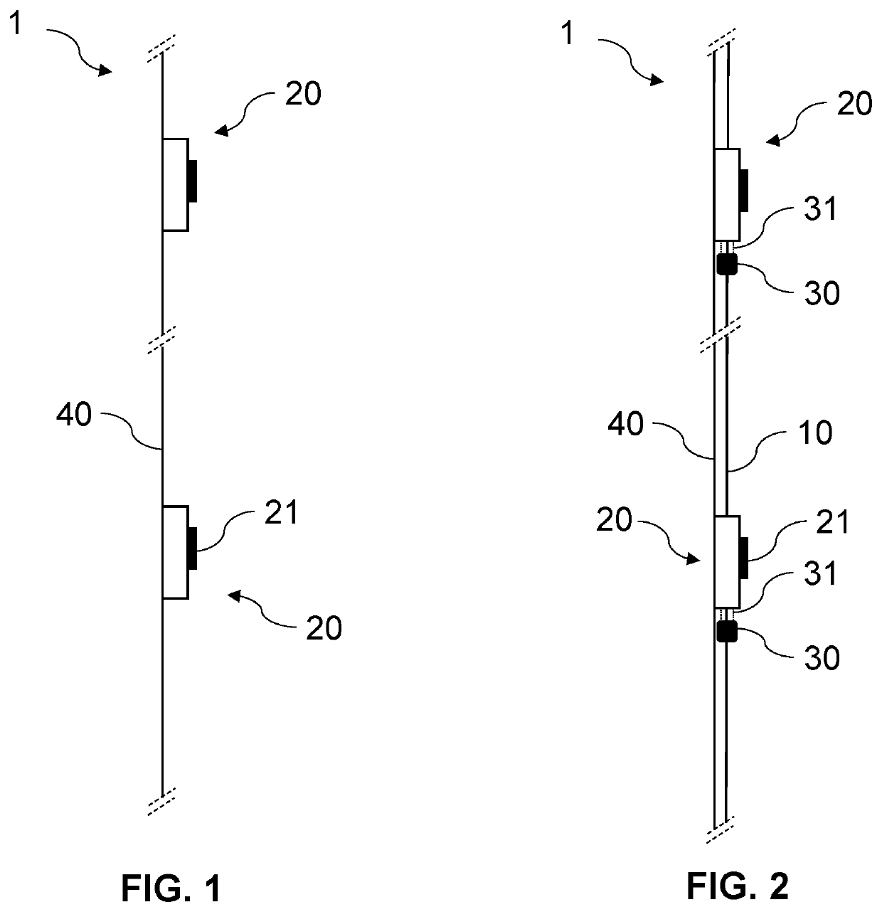
[0056]In the remainder of the description, the expression “blockage point” corresponds to the jamming of a tubular member, for example in a borehole, preventing this tubular member from advancing. A blockage point may, for example, be the result of a rockfall, restriction, or deformation of the rock formation.

[0057]By “drilling”, within the meaning of the invention, is meant the action of drilling and / or its result.

[0058]By “position”, within the meaning of the invention, is meant a precise location in the space occupied by the blockage point, for example over the entire height of the borehole, and therefore more particularly a depth or distance from the surface.

[0059]The term “tubular member”, within the meaning of the invention, preferably corresponds to a drill rod used for drilling a well, a casing, or tubing. However, a tubular member may also correspond to a part, object, or conduit, the length of which is greater than the width, for example cylindrical or rectangular in shape...


PUM


Abstract

The invention relates to a maintenance device (1) for determining the position of a blockage point (2) of a tubular member (3), characterized in that it includes a fiber-optic cable (40) and a plurality of holding guides (20), each holding guide (20) being attached to the fiber-optic cable (40) and including a means (21) for attaching to the tubular member (3).The invention also relates to a method and a system for determining the position of a blockage point of a tubular member.

Description

[0001]The invention relates to the field of subsoil exploitation such as mining and oil exploitation, and more particularly to the field of drilling. The invention relates to a maintenance device for determining the position of a blockage point of a tubular member, preferably in a borehole. The invention also relates to a method for determining the position of a blockage point of a tubular member in a borehole.PRIOR ART[0002]Drilling has been used for years to dig holes in the earth. Generally speaking, drilling refers to all the techniques for digging or drilling the earth to great depths, as well as the result of their application. Historically, drilling has made it possible to find and exploit resources such as water. Then, over the years, drilling techniques developed with the exploitation of other resources such as oil and gas. New fields of application using drilling techniques have also emerged, such as geothermal energy, geotechnics, the environment, and also scientific rese...

Claims


Application Information

Patent Timeline
Patent Type & Authority Patents(United States)
IPC IPC(8): E21B47/09E21B47/002E21B47/135E21B47/01
CPCE21B47/09E21B47/0025E21B47/01E21B47/135
Inventor LANTICQ, VINCENTCLÉMENT, PIERRELAMAZOUADE, TAREK MARIONSOUCHAL, RAPHAËLCABÉ, CÉDRIC
Owner FEBUS OPTICS
Why Eureka
Try Eureka