Supercharge Your Innovation With Domain-Expert AI Agents!

Coriolis mass flow meter

a mass flow meter and coriolis technology, applied in the field ofco, can solve the problems of long time, design difficulties, and ultimately measurement-related problems, and achieve the effect of reducing the time of measurement and measuremen

Active Publication Date: 2022-07-19
HEINRICHS MESSTECHN
View PDF24 Cites 0 Cited by
  • Summary
  • Abstract
  • Description
  • Claims
  • Application Information

AI Technical Summary

Benefits of technology

The present invention aims to provide a Coriolis mass flow meter that is simpler and more scalable for small sizes, which means it can measure small amounts of fluid accurately.

Problems solved by technology

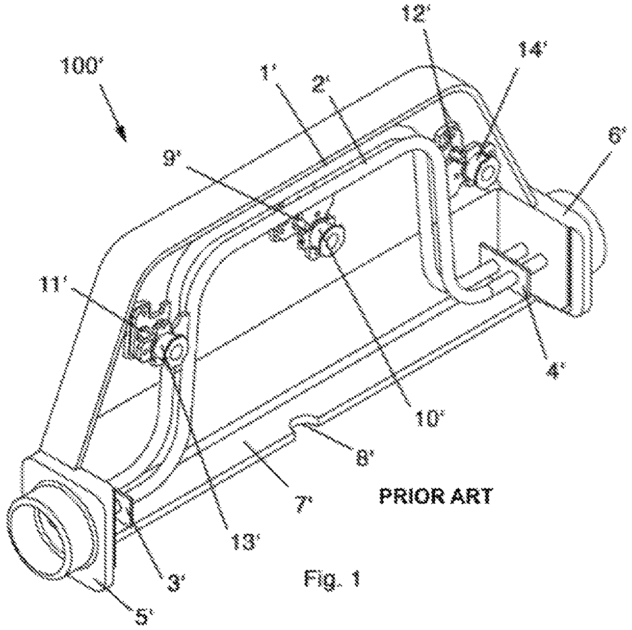
However, the smaller a Coriolis mass flow meter 100′ according to the prior art becomes, the more design and ultimately measurement-related problems arise, because while most of the components of the device can also be made smaller when the meter 100′ is made smaller (in accordance with the measurement range), such as the measurement tubes 1′, 2′, the magnets 9′, 11′, 12′, the coupling elements 3′, 4′ etc. and even the housing 7′, a scaling down to small sizes for the coils 10′, 13′,14′ of the vibration exciters and vibration sensors and accordingly for their fastening elements on the measurement tubes 1′, 2′, the so-called coil holders, is no longer so easily possible.
Both have various unfavourable measurement properties of these devices and lead to design difficulties in the case of small Coriolis mass flow meters according to the prior art.
However, this arrangement is also not easily scalable to smaller sizes, because with smaller measurement arrangements, even minor inaccuracies in the construction, for example in the positioning of the magnets or the gusset plates, have a relatively increasing influence on the measurement accuracy.
The diameter of the coil wire would then be so thin that it could hardly be wound and that sudden wire breaks on the connecting wires which connect the coil to the continued lines inside the device could or would occur.
Such wire breaks are a common occurrence, even in very large devices, because in Coriolis mass flow meters according to the prior art, the connecting wires always vibrate together with the coils, more or less in an uncontrolled manner, which leads to problems even in meters with correspondingly large dimensions and is no longer manageable for small meters in a correspondingly small measurement range.
The fact that coils, coil wire and coil holder cannot be reduced to any size, however, causes further problems in small Coriolis mass flow meters according to the prior art.
From a certain size, coiling and coil holding become very heavy compared to the measurement tubes themselves.
The devices then operate in ranges of very low frequencies, e.g. near 100 Hz or even lower, which makes the devices not only less accurate but also very sensitive to external influences such as, for example, vibrations, shock waves, etc.
Furthermore, the local increase in mass due to the coils and the coil holders causes very high jumps in mass in the “measurement tube-fluid-coil-coil holder” system, so that there are various inherent dynamic modes during operation that further distort the measurement result.
A further problem also arises in small Coriolis mass flow meters according to the prior art due to the reduction in size.
As a result, small devices are in most cases more difficult to manufacture and usually less accurate than larger devices.
This means that the measurement tubes are deflected from an unstable state and tend (due to the instability, similar to a pressure rod that can break out in any direction), to superimpose the vibration of the measurement tubes in the opposite direction (i.e. the measurement-relevant vibration) with additional deflections that randomly change in any direction (in other words: to “contaminate”) and thus distort the measurement results.
These harmful deflections are so small that they are generally not visible to the naked eye.
However, they can influence the vibration behaviour and—especially in the case of small measurement arrangements—can lead to significant measurement inaccuracies.
This counteracts undesirable vibrations of the circuit board.
In the case of a thin weld seam, this can be very complex and technically difficult.

Method used


Image

  • Coriolis mass flow meter
  • Coriolis mass flow meter
  • Coriolis mass flow meter

Examples


Embodiment Construction

[0054]FIG. 2 shows in perspective a Coriolis mass flow meter 100 according to a preferred embodiment of the present invention without the housing cover 30 (shown in FIG. 9). On a housing body 10, which has a flow inlet 31 and a flow outlet 32 for a fluid medium, two measurement tubes 23, 24 are spaced apart from each other and in parallel and are fastened to the housing body 10 and connect the flow inlet 31 and the flow outlet 32 to each other.

[0055]An electromagnetic coil 2 is provided for the first measurement tube 23 as an electrically controllable vibration exciter 42, and an electromagnetic coil 5 is provided for the second measurement tube 24 as an electrically controllable vibration exciter 45. Each of the vibration exciters 42,45 is designed to cause the measurement tube 23, 24 in front of which it is arranged to vibrate.

[0056]Furthermore, in the exemplary embodiment shown, two electrically controllable vibration sensors 41, 43 (visible in FIG. 3, hidden in FIG. 2), 44, 46 a...


PUM


Abstract

A coriolis mass flow meter, including: a housing body, having a flow inlet and flow outlet for a fluid medium, two measurement tubes, which are spaced apart from each other fastened to the housing body connecting the flow inlet and the flow outlet to each other, at least one electrically controllable vibration exciter for each measurement tube (23, 24), the vibration exciter being designed to cause the measurement tube to vibrate, and at least two electrically controllable vibration sensors, the vibration sensors being designed to sense the vibration of at least one of the two measurement tubes. The vibration exciter vibration sensors are spatially fixedly fastened to the housing body between the two measurement tubes and are designed as electromagnetic coils. Each coil interacts with a permanent magnet fastened to one of the measurement tubes. The permanent magnets are oriented in such a way that permanent magnets attract each other.

Description

CROSS REFERENCE TO RELATED APPLICATIONS[0001]This application is a National Phase of PCT Patent Application No. PCT / EP / 2018 / 082571 having International filing date of Nov. 26, 2018, which claims the benefit of priority of European Application No. 17205791.1 filed on Dec. 7, 2017 entitled CORIOLIS MASS FLOW METER. The contents of the above applications are all incorporated by reference as if fully set forth herein in their entirety.BACKGROUND[0002]The invention relates to a Coriolis mass flow meter according to the preamble of claim 1 having a housing body, which has a flow inlet and a flow outlet for a fluid medium, and two measurement tubes, which are spaced apart from each other, preferably in parallel, and are fastened to the housing body and connect the flow inlet and the flow outlet to each other, so that a fluid medium to be measured flows from the flow inlet through the measurement tube to the flow outlet, i.e. in other words, the measurement tubes connect the flow inlet and ...

Claims


Application Information

Patent Timeline
Patent Type & Authority Patents(United States)
IPC IPC(8): G01F1/84
CPCG01F1/8477G01F1/8422G01F1/8427G01F1/8431G01F1/8409
Inventor CHATZIKONSTANTINOU, THOMAS
Owner HEINRICHS MESSTECHN
Features
  • R&D
  • Intellectual Property
  • Life Sciences
  • Materials
  • Tech Scout
  • Unparalleled Data Quality
  • Higher Quality Content
  • 60% Fewer Hallucinations
Learn More