
Stemless prosthesis anchor components and kits

a technology of stemless prosthesis and components, which is applied in the field of stemless prosthesis anchor components of joint prosthesis, can solve the problems of limiting the distance between the humerus and the glenoid, and inset positioning can compromise the integrity of the fixation into the humerus, so as to improve the ability of the surgeon to position, minimize the risk of dislocation of the shoulder joint or acromion fracture, and improve the soft tissue tension

Active Publication Date: 2022-08-02
HOWMEDICA OSTEONICS CORP
View PDF323 Cites 0 Cited by
  • Summary
  • Abstract
  • Description
  • Claims
  • Application Information

AI Technical Summary

Benefits of technology

The solution provides improved control over soft tissue tension, reduces the risk of dislocation and fractures, and offers excellent long-term fixation by allowing greater flexibility in humeral positioning and bone preservation during implantation.

Problems solved by technology

This intermediate component, which is sometimes called a tray, adds thickness to the assembly and can therefore limit how close the humerus can be placed to the glenoid following a reverse shoulder implant procedure.
While a stemless humeral anchor could be inset into the epiphysis of the humerus inferior of the resection plane to provide a larger range of the position of the humerus to the glenoid, inset positioning can compromise the integrity of the fixation into the humerus.

Method used


Image

  • Stemless prosthesis anchor components and kits
  • Stemless prosthesis anchor components and kits
  • Stemless prosthesis anchor components and kits

Examples


Embodiment Construction

[0042]While the present description sets forth specific details of various embodiments, it will be appreciated that the description is illustrative only and should not be construed in any way as limiting. Furthermore, various applications of such embodiments and modifications thereto, which may occur to those who are skilled in the art, are also encompassed by the general concepts described herein. Each and every feature described herein, and each and every combination of two or more of such features, is included within the scope of the present invention provided that the features included in such a combination are not mutually inconsistent.

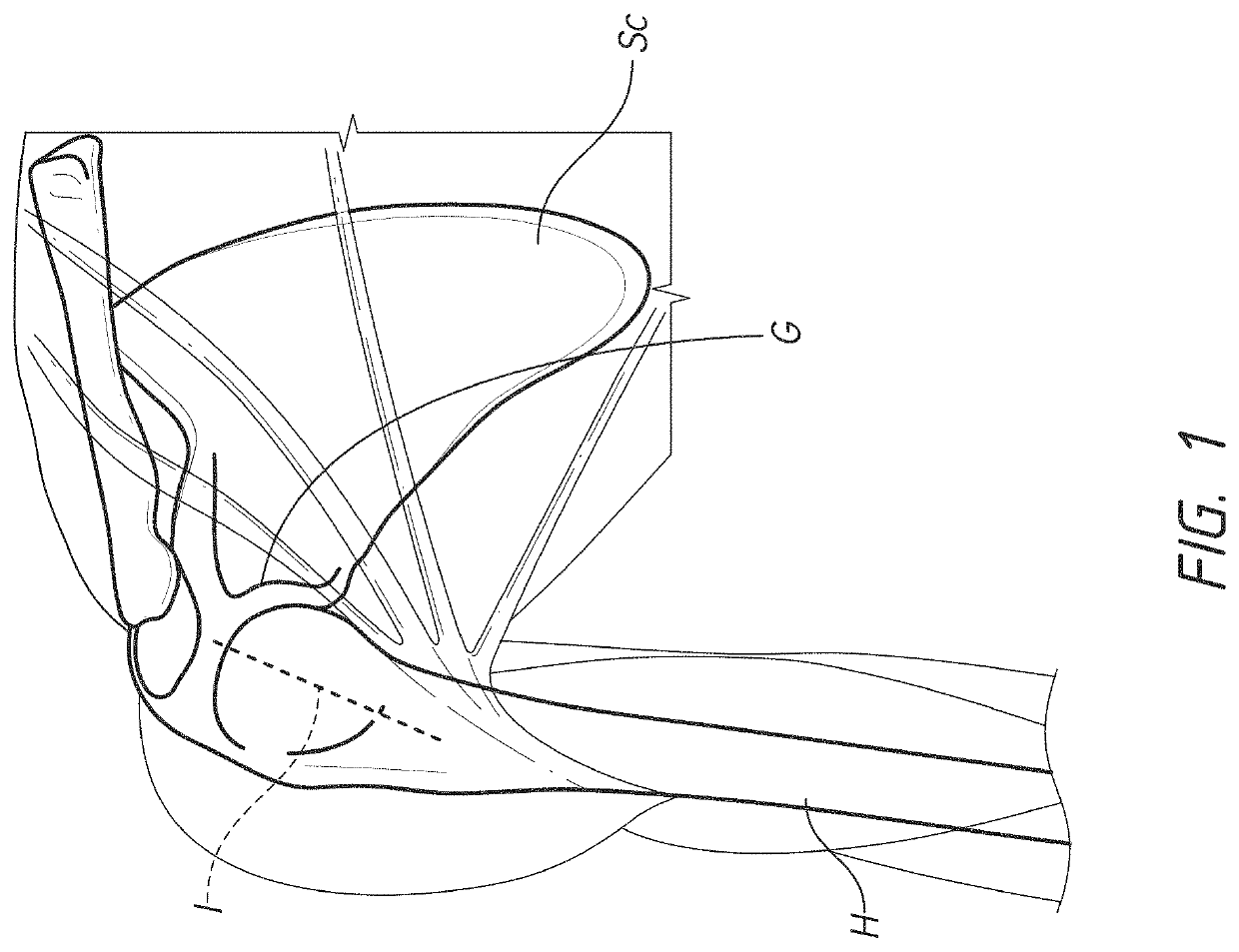
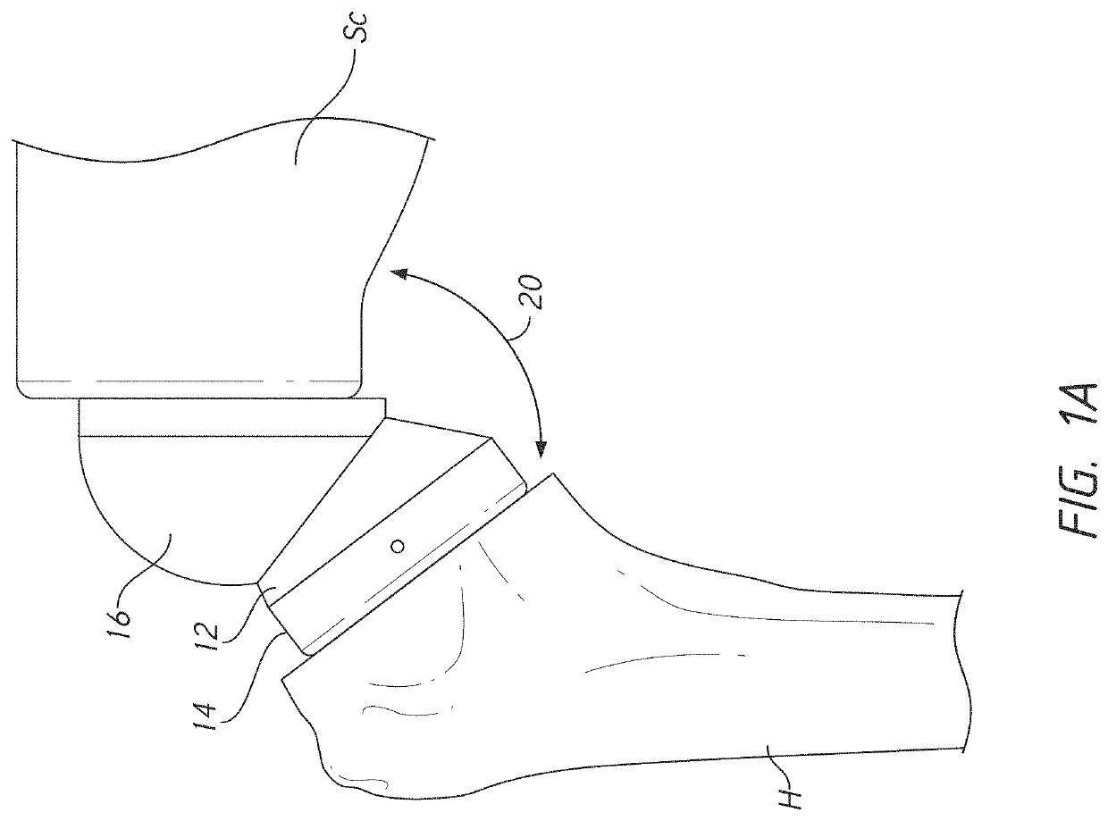
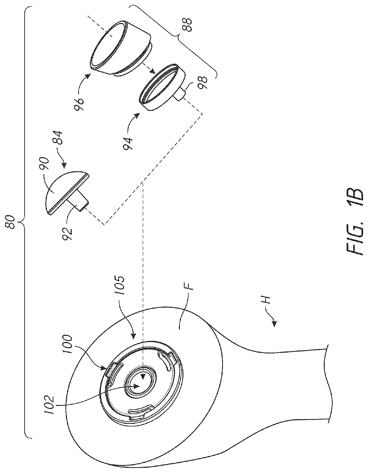
[0043]This application is directed to shoulder implants that provide greater control of the soft tissue tension around the joint following implantation. The improvements herein enable a patient to have an appropriate level of tension in the soft tissue to provide good range of motion while reducing the risk of dislocation of the shoulder joint or...


PUM


Abstract

A prosthesis assembly is provided that includes a base member that has a helical structure and a cylindrical member opposite the helical structure. The cylindrical member is configured for direct connection with a reverse insert of a reverse shoulder assembly. The cylindrical member is configured for direct connection with a reverse insert spacer in some embodiments. The reverse insert can be inserted into a space defined at least in part by a wall of the cylindrical member and an inferior wall of the of the base member. The helical structure extends between a first end and a second end. The base member also can include one or more pathways. The pathway(s) is accessible from the second end and is directed toward the first end through the helical structure. The pathway is located inward of an outer periphery of the helical structure, e.g., adjacent to an inner periphery of the helical structure. The pathway extends in a space between successive portions of the helical structure. The prosthesis assembly can include a locking device that has a support member and an arm that projects away from the support member. The arm is configured to be disposed in the pathway when the support member is disposed adjacent to the second end of the base member. The arm is disposed through bone in the space between successive portions of the helical structure when the prosthesis assembly is implanted.

Description

INCORPORATION BY REFERENCE TO ANY PRIORITY APPLICATIONS[0001]Any and all applications for which a foreign or domestic priority claim is identified in the Application Data Sheet as filed with the present application are hereby incorporated by reference under 37 C.F.R. § 1.57.BACKGROUND OF THE INVENTIONField of the Invention[0002]The present disclosure relates to a stemless prosthesis anchor component of a joint prosthesis that can be coupled with a concave articular body such as is used in reverse shoulder arthroplasty.Description of the Related Art[0003]Skeletal joints have a variety of configurations providing for a wide range of smooth movement of two or more bones relative to each other. For example, in a shoulder joint, the head of the humerus interacts with the glenoid cavity of the scapula in a manner similar to a “ball and socket” joint. Over time, it may become necessary to replace a joint, such as the shoulder joint, with a prosthetic joint. The prosthetic joint can include...

Claims


Application Information

Patent Timeline
Patent Type & Authority Patents(United States)
IPC IPC(8): A61F2/40A61F2/30A61B17/15A61B17/16A61F2/46A61F2/00
CPCA61F2/4003A61F2/30767A61F2/4014A61B17/15A61B17/1684A61F2/0077A61F2/30771A61F2/4081A61F2/4612A61F2002/305A61F2002/3085A61F2002/30224A61F2002/30289A61F2002/30354A61F2002/30357A61F2002/30476A61F2002/30484A61F2002/30594A61F2002/30599A61F2002/30604A61F2002/30607A61F2002/30616A61F2002/30632A61F2002/30667A61F2002/4018A61F2002/4022A61F2002/4074
Inventor KNOX, KEVIN P.GARGAC, SHAWN M.MUTCHLER, AUSTIN WYATTCOLLINATHWAL, GEORGE S.
Owner HOWMEDICA OSTEONICS CORP
Learn More