Supercharge Your Innovation With Domain-Expert AI Agents!

Liquid matrix shear pressure impregnator applications

a technology of impregnator and liquid matrix, which is applied in the direction of coatings, layered products, etc., can solve problems such as matrix degradation

Active Publication Date: 2022-08-02
FRAM JERRY R
View PDF21 Cites 0 Cited by
  • Summary
  • Abstract
  • Description
  • Claims
  • Application Information

AI Technical Summary

Benefits of technology

The patent is about a device that is used to impregnate a material with a liquid. In one embodiment, the device has a mechanism that allows for easy cleanup without the need for scrapers. In another embodiment, the device eliminates a pressure barrier that could affect the performance of the device. The technical effects of these improvements include easier maintenance and more reliable operation of the device.

Problems solved by technology

However, in some cases such shear forces degrade the matrix.

Method used


Image

  • Liquid matrix shear pressure impregnator applications
  • Liquid matrix shear pressure impregnator applications
  • Liquid matrix shear pressure impregnator applications

Examples


Embodiment Construction

[0055]1. Overview

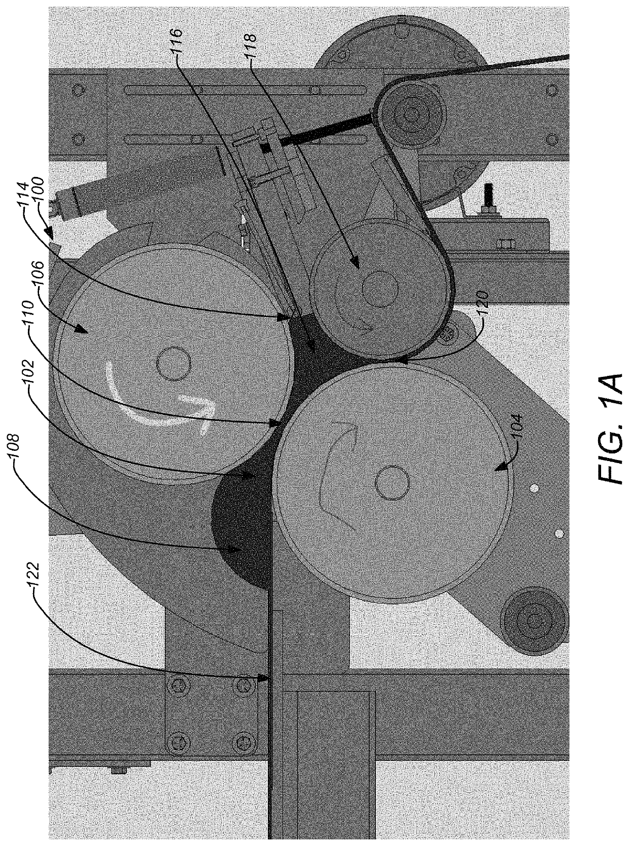
[0056]U.S. Pat. No. 8,273,286, by Fram, incorporated by reference herein, discloses systems and methods where at least one roller (e.g., a kicker roller) is used to impregnate fibers (i.e., a charge or reinforcement) with a liquid resin (i.e., matrix) by eliminating air from the resin and fibers as they enter a pressurized zone. Air is forced out as the resin is first drawn into an entry zone of the roller, then into an “entry gap” adjacent to the roller, and then into the “pressure zone” on the opposite side of the roller. The “pressure zone” is an enclosed area at the output side of the roller. The resin and fiber combination is then forced out through a small “exit gap.” Shear forces between the surface of the quickly rotating driven roller and the resin provide the driving force pressurizing the matrix. The fibers may be continuous (e.g., mat from a roll) or discontinuous, for example, loose cut.

[0057]However, the systems and methods of the prior art do not prov...


PUM

PropertyMeasurementUnit
enclosed volumeaaaaaaaaaa
volumeaaaaaaaaaa
shear forcesaaaaaaaaaa

Abstract

Systems and methods are described where a volume receiving a liquid matrix and fibers at an inlet where opposing sides of the volume converge to form a gap and a moving surface in contact with the liquid matrix and the fibers and moving with respect to the liquid matrix and the fibers through the gap such that shear force is transferred to the liquid matrix and the fibers pushing the liquid matrix and the fibers forward through the gap, creating currents in the liquid matrix and increasing pressure. The increased pressure within the volume forms a barrier to entrained gases within the liquid matrix such that the entrained gases are inhibited from passing through the gap along with the liquid matrix and the fibers.

Description

BACKGROUND OF THE INVENTION1. Field of the Invention[0001]Embodiments of the invention relate to the continuous manufacture of fiber-reinforced composite materials, particularly in a sheet form. Embodiments of this invention relate to the use of shear forces from moving surfaces in contact with the liquid together with a confinement means to create regions of elevated pressure through which the materials pass. The elevated pressures inhibit entrained air and / or other gases from following the liquid and fibers through impregnation, thus excluding them from the product and improving wetout. Furthermore, currents generated by these shear forces can make the distribution of suspended fibers and fillers in the final product more uniform.[0002]In cases where the liquid can sustain high shear forces, the surfaces in contact with the liquid can move very rapidly to powerfully wet out the fibers under high pressure and strong currents. However, the same concepts can be used to gently impregn...

Claims


Application Information

Patent Timeline
Patent Type & Authority Patents(United States)
IPC IPC(8): B32B5/26B29C70/50B29C48/08B29C70/48
CPCB29C70/504B29C48/08B32B5/26B29C70/48B32B2260/046B29B15/125B29C70/28B29C48/16B29C48/0022B29C48/2886
Inventor FRAM, JERRY R.
Owner FRAM JERRY R
Features
  • R&D
  • Intellectual Property
  • Life Sciences
  • Materials
  • Tech Scout
  • Unparalleled Data Quality
  • Higher Quality Content
  • 60% Fewer Hallucinations
Learn More