
Projecting apparatus

a projecting apparatus and projecting technology, applied in the direction of instruments, optical elements, fluid speed measurement, etc., can solve the problems of different shrinkage amounts of adhesives, and achieve the effect of improving the problem

Active Publication Date: 2022-08-02
MEGA 1 CO LTD
View PDF9 Cites 0 Cited by
  • Summary
  • Abstract
  • Description
  • Claims
  • Application Information

AI Technical Summary

Benefits of technology

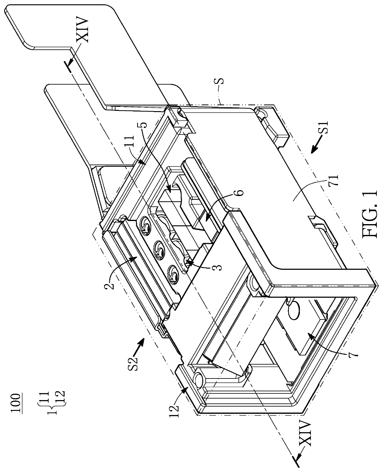
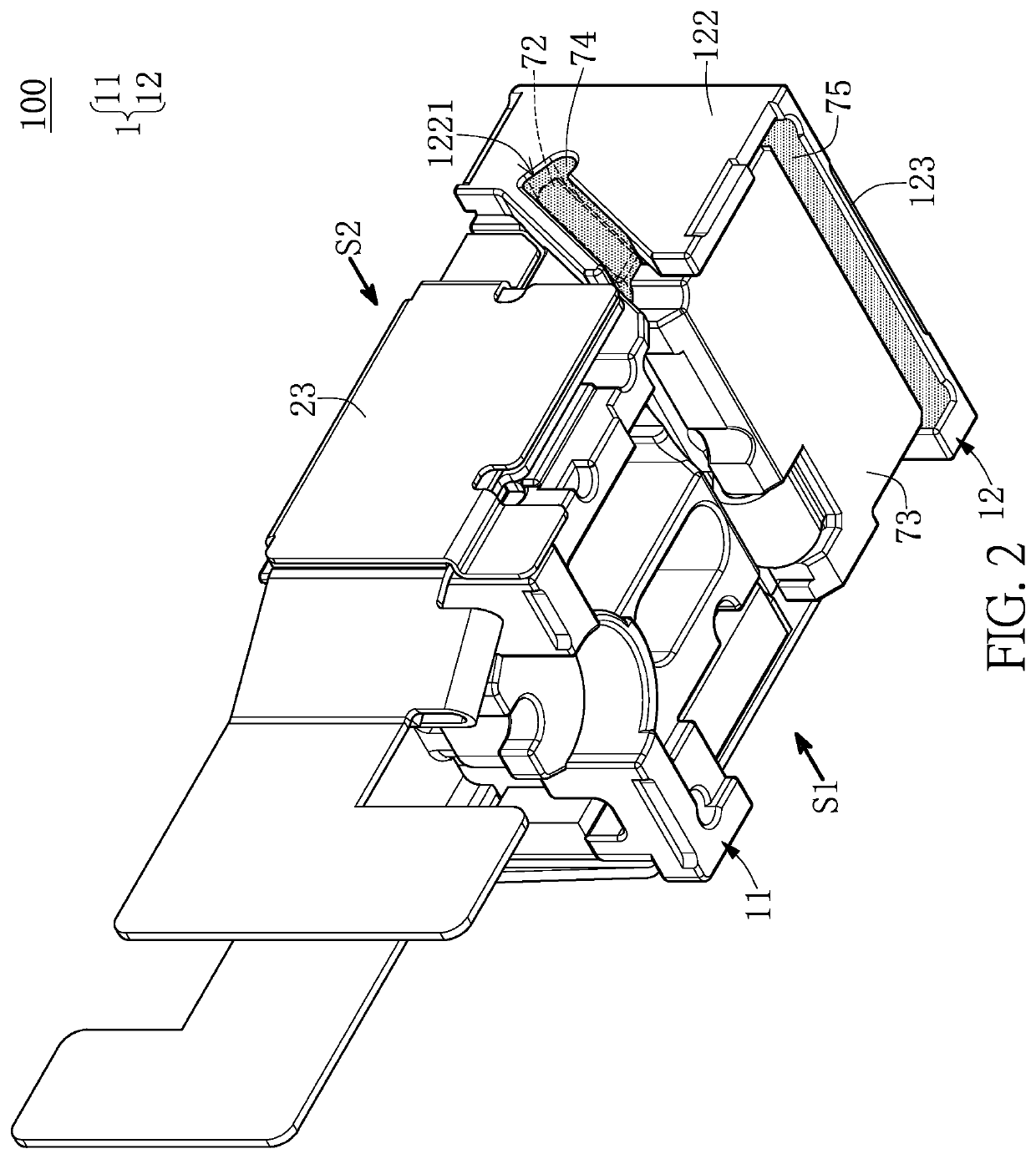
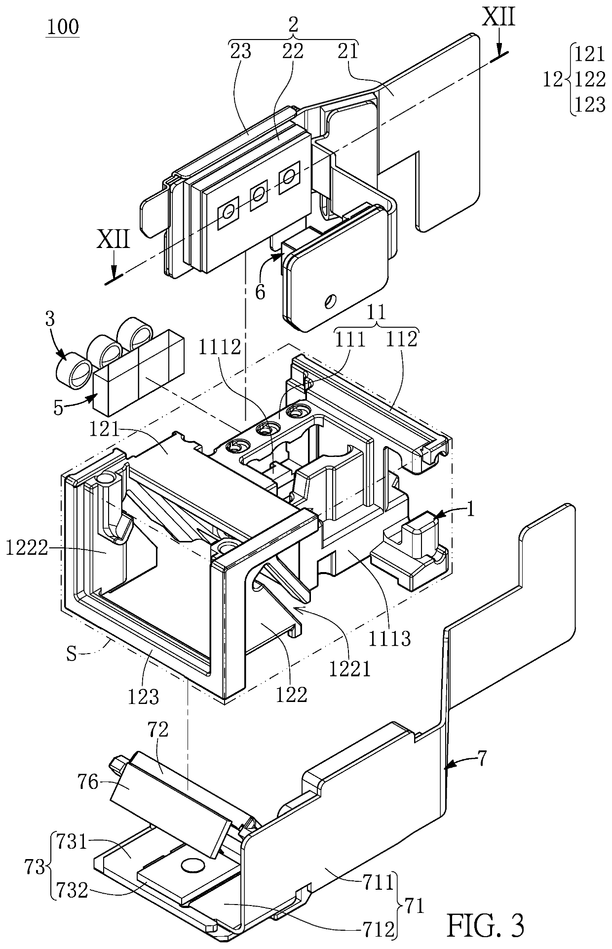
The present invention provides a projecting apparatus that overcomes the limitations of conventional projecting apparatuses. This is achieved by fixing a collimator lens to a carrying bridge using an adhesive that has predictable volume and shrinkage direction. This helps control the offset of the collimator lens, improving the accuracy of the assembly.

Problems solved by technology

However, the adhesives have different amounts of shrinkage after solidification, which easily causes the collimator lens fixed by the adhesives to offset along different directions corresponding to the adhesives.

Method used


Image

  • Projecting apparatus
  • Projecting apparatus
  • Projecting apparatus

Examples


Embodiment Construction

[0025]The present disclosure is more particularly described in the following examples that are intended as illustrative only since numerous modifications and variations therein will be apparent to those skilled in the art. Like numbers in the drawings indicate like components throughout the views. As used in the description herein and throughout the claims that follow, unless the context clearly dictates otherwise, the meaning of “a”, “an”, and “the” includes plural reference, and the meaning of “in” includes “in” and “on”. Titles or subtitles can be used herein for the convenience of a reader, which shall have no influence on the scope of the present disclosure.

[0026]The terms used herein generally have their ordinary meanings in the art. In the case of conflict, the present document, including any definitions given herein, will prevail. The same thing can be expressed in more than one way. Alternative language and synonyms can be used for any term(s) discussed herein, and no speci...


PUM


Abstract

A projecting apparatus is provided, and includes a frame, a light source module, at least one collimator lens, at least one adhesive, and a microelectromechanical systems (MEMS) module. The frame includes a first frame portion and a second frame portion. The first frame portion has a carrier and a carrying bridge having an end connected to the carrier. The frame has a processing slot that uses the carrying bridge as a bottom thereof, and the carrying bridge has at least one thru-hole that is in spatial communication with the processing slot. The second frame portion is connected to the carrier and another end of the carrying bridge of the first frame portion. The at least one adhesive corresponds in position to the at least one thru-hole, and connects the at least one collimator lens onto the carrying bridge. The MEMS module is disposed on the second frame portion.

Description

CROSS-REFERENCE TO RELATED PATENT APPLICATION[0001]This application claims priority to the U.S. Provisional Patent Application Ser. No. 63 / 031,589 filed on May 29, 2020, the U.S. Provisional Patent Application Ser. No. 63 / 031,594 filed on May 29, 2020, the U.S. Provisional Patent Application Ser. No. 63 / 031,593 filed on May 29, 2020, the U.S. Provisional Patent Application Ser. No. 63 / 031,592 filed on May 29, 2020, which application are incorporated herein by reference in its entirety.[0002]Some references, which may include patents, patent applications and various publications, may be cited and discussed in the description of this disclosure. The citation and / or discussion of such references is provided merely to clarify the description of the present disclosure and is not an admission that any such reference is “prior art” to the disclosure described herein. All references cited and discussed in this specification are incorporated herein by reference in their entireties and to the...

Claims


Application Information

Patent Timeline
Patent Type & Authority Patents(United States)
IPC IPC(8): G03B21/14G02B27/30G02B27/01G02B26/08G02B7/02B81B7/00G03B21/00
CPCG03B21/145B81B7/008G02B7/025G02B26/0833G02B27/0172G02B27/30G03B21/008B81B2201/042G02B2027/0178G03B21/14G02B7/02G02B7/021G02B27/017G03B21/16
Inventor MASUDA, MAKOTOWU, WEN-CHIEHHO, HSIANG-CHENYEN, CHIH-HANYANG, CHIH-YU
Owner MEGA 1 CO LTD
Learn More