Photonic coherent detection array

a detection array and photonic technology, applied in the field of optical coherent detection, can solve the problems of affecting the efficiency of coherent detection, limiting the number of pixels in the detection array, and the described nci scheme may be limited to a few pixels, so as to facilitate the stacking of detection units and the scalability of coherent detection array, and high frame rate operation. the effect of high pixel coun

Active Publication Date: 2022-08-02
OAM PHOTONICS LLC
View PDF6 Cites 0 Cited by
  • Summary
  • Abstract
  • Description
  • Claims
  • Application Information

AI Technical Summary

Benefits of technology

[0007]Embodiments of the present invention describe a coherent detection array implemented on a photonic integrated circuit (PIC) and multiplexing methods for readout of coherent detection signals that leverage the properties of the detection array. The coherent detection array may comprise a plurality of coherent detection units coupling with connecting waveguides and electrical conducting paths, wherein local oscillator (LO) light is introduced into the coherent detection units through the connecting waveguides. The detection units may be configured to include free-space-to-waveguide couplers to receive incident signal light from a medium, including but not limited to free space, into the detection units, optical couplers that mix the signal light with the LO light, and photodetectors that measure the mixed signal-LO light. The electrical conducting paths may manifest as readout channels for multiplexing electrical signals, wherein the readout channels may facilitate stacking of the detection units and scalability of the coherent detection array without the need of complex waveguide routing nor optical switching. The coherent detection array also enables multiplexing methods that may leverage extra degrees of freedom of the coherent detection array. These methods may include those enabled by the local oscillator and those related to the properties and responses of the components of the PIC-based detection array. The scalable design of the coherent detection array together with multiplexing methods applicable to the array may enable the coherent detection array to achieve high pixel-count and high frame-rate operation simultaneously.

Problems solved by technology

Such a configuration however is bulky and gives rise to the issue of the spatial-mode matching of the incoming signal beam with the LO beam that may affect the efficiency of the coherent detection.
Consequently, the described NCI scheme may be limited to a few pixels in the case where size and cost are at a premium.
However, these detection arrays still have to transfer the pixel signals row-by-row to the horizontal registers of the column addressing circuit.
State-of-the-art CMOS-based direct detection arrays implemented with in situ frame storage are able to operate at very high sampling rates, but the frame storage circuitry substantially constraints the number of pixels in the detection array.
Generally, existing designs of either coherent or direct detection arrays and their operations encounter a trade-off between the pixel count and the frame rate.

Method used


Image

  • Photonic coherent detection array
  • Photonic coherent detection array
  • Photonic coherent detection array

Examples


first preferred embodiment

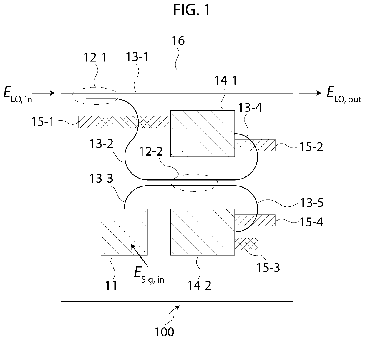
[0025]A coherent detection unit 100 according to the present preferred embodiment will be described with reference to FIG. 1, which illustrates a plan view of the coherent detection unit 100. The coherent detection unit 100 illustrated in FIG. 1 is configured to include a free-space-to-waveguide coupler 11, optical couplers 12-1 and 12-2, waveguides 13-1, 13-2, 13-3, 13-4 and 13-5, photodetectors 14-1 and 14-2, and electrodes 15-1, 15-2, 15-3 and 15-4. The coherent detection unit 100 may also be configured to include additional components, such as one or more modulators and / or heaters, which may be used to modulate or modify the properties of the coherent detection unit. These additional components are not shown in FIG. 1. The coherent detection unit 100 may be integrated on a substrate 16 using optical waveguide technology.

[0026]The waveguide 13-1 is an optical waveguide having one end (incoming end) through which the local oscillator light ELO,in may be introduced, and having anot...

second preferred embodiment

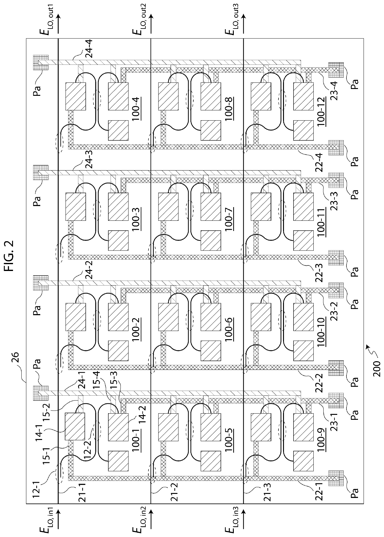
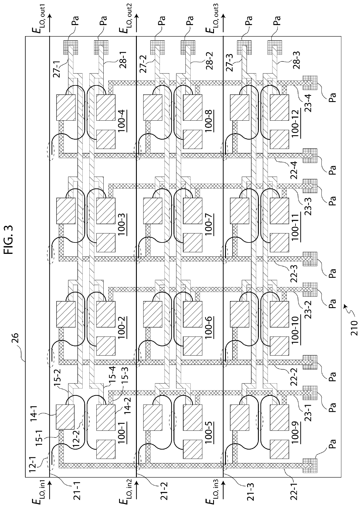
[0035]Two examples of coherent detection arrays 200 and 210 according to the present preferred embodiment will be described with reference to FIGS. 2 and 3.

[0036]FIG. 2 illustrates a plan view of the coherent detection array 200. The coherent detection array 200 is configured to include plural units of the coherent detection unit 100 according to the embodiment illustrated in FIG. 1. In some aspects, the coherent detection array 200 may include other embodiments of the coherent detection units. In some aspects, the coherent detection array 200 may be constructed by concatenating plural units of the coherent detection unit 100 in a rectilinear configuration. In other aspects, embodiments of the coherent detection array may be constructed by concatenating plural units of the coherent detection unit 100 in geometries other than the rectilinear configuration. The coherent detection array 200 may be integrated on a substrate 26 using optical waveguide technology.

[0037]In some aspects of ...

third preferred embodiment

[0063]Two examples of coherent detection units 300 and 310 according to the present preferred embodiment will be described with reference to FIGS. 4 and 5.

[0064]FIG. 4 illustrates a plan view of the coherent detection unit 300. The coherent detection unit 300 illustrated in FIG. 4 is configured to include a free-space-to-waveguide coupler 31, optical couplers 32-1 and 32-2, waveguides 33-1, 33-2, 33-3 and 33-4, a photodetector 34, and electrodes 35-1 and 35-2. The coherent detection unit 300 may also be configured to include additional components, such as one or more modulators and / or heaters, which may be used to modulate or modify the properties of the coherent detection unit. These additional components are not shown in FIG. 4. The coherent detection unit 300 may be integrated on a substrate 36 using optical waveguide technology.

[0065]The coherent detection unit 300 is a modified version of the coherent detection unit 100 illustrated in FIG. 1. The coherent detection unit 300 may...


PUM


Abstract

The present invention relates to a coherent detection array and methods of multiplexing for signal readout of the coherent detection array. The coherent detection array may be implemented on a photonic integrated circuit (PIC). It may comprise a plurality of coherent detection units coupling with connecting waveguides and electrical conducting paths, wherein the electrical conducting paths may manifest as readout channels for multiplexing electrical signals. The detection units may be configured to include free-space-to-waveguide couplers, optical couplers, and photodetectors. The coherent detection array enables multiplexing methods that may leverage extra degrees of freedom of the coherent detection array. These methods may include those enabled by the local oscillator and those related to the properties and responses of the components of the PIC-based detection array.

Description

CROSS-REFERENCE TO RELATED APPLICATION[0001]This application claims the benefit of U.S. Provisional Patent Application No. 62 / 889,065 filed on Aug. 20, 2019, which is incorporated by reference herein in its entirety.FIELD OF THE INVENTION[0002]The present invention relates to optical coherent detection and, in particular, relates to detection arrays for optical coherent detection.BACKGROUND[0003]Optical coherent detection, also known as optical heterodyne detection, is able to measure both the field amplitude and phase of an optical signal relative to a reference light signal, customarily called the local oscillator (LO), whereas direct optical detection measures only the light intensity of the optical signal. Advantages of coherent detection include near shot-noise-limited optical amplification, rejection of background light and provision of additional information through the phase.[0004]A detection array, commonly called a focal plane array (FPA) when used at the focal plane of an...

Claims


Application Information

Patent Timeline
Patent Type & Authority Patents(United States)
IPC IPC(8): G03H1/26
CPCG03H1/2645G03H2001/267G03H2001/2665G03H2001/2675G01S17/34G02B6/12004G02B2006/12107G02B2006/12123G02B2006/12147G01S7/4816G01S7/4818G02F2201/58G02F2201/302G02F1/225
Inventor CHAN, KAM WAI CLIFFORDWONG, CHUNG KI
Owner OAM PHOTONICS LLC
Why Eureka
Try Eureka