
Shower head fixture

a shower head and shower head technology, applied in water installations, spray nozzles, constructions, etc., can solve problems such as unenvironmental protection, achieve the effect of improving the water-saving effect of the shower head, and low water pressure environmen

Active Publication Date: 2022-08-09
XIAMEN LOTA INT CO LTD
View PDF20 Cites 0 Cited by
  • Summary
  • Abstract
  • Description
  • Claims
  • Application Information

AI Technical Summary

Benefits of technology

[0005]The present invention provides a shower head assembly which can increase the force of the outflow of water or discharge water effectively. The discharged water flow is grouped or arranged to provide “bubble water flow” that feels soft and comfortable to the user or person taking a shower under the inventive shower head. The discharged water flow avoids random spray that conserves water and improves the water-saving effect of the shower head. The shower head of the present invention is also suitable for low water pressure environment.
[0011]According to another aspect of the invention, a switching device is installed to the main body for controlling an outflow of water from the face plate. The face panel of the present invention has a plurality of water outlet units, wherein each water outlet unit includes a plurality of jet orifices. The water discharged or flowing from the plurality of jet orifices forms a bunched or arranged spout of discharged water flow that includes a plurality of fine spouts that avoids random, inefficient spray. Since the diameter of the jet orifice is small, the force of the fine spouts is strong and the water-saving effect of the shower head is good. The shower head of the present invention can be used for low pressure water environments.

Problems solved by technology

Numerous existing shower heads provide discharged water flow that does not provide physical ease and relaxation, instead, the water flow sprays in an uneven pattern that wastes some water, and is not environmentally friendly.

Method used


Image

  • Shower head fixture
  • Shower head fixture
  • Shower head fixture

Examples


Embodiment Construction

[0023]Embodiments of the present invention will now be described, by way of example only, with reference to the accompanying drawings.

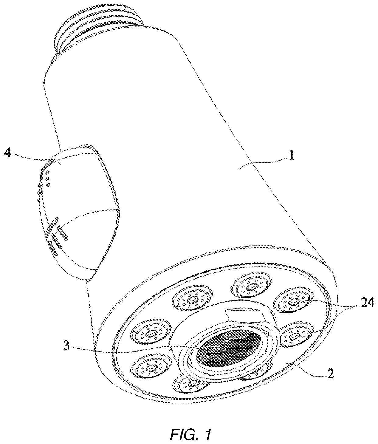
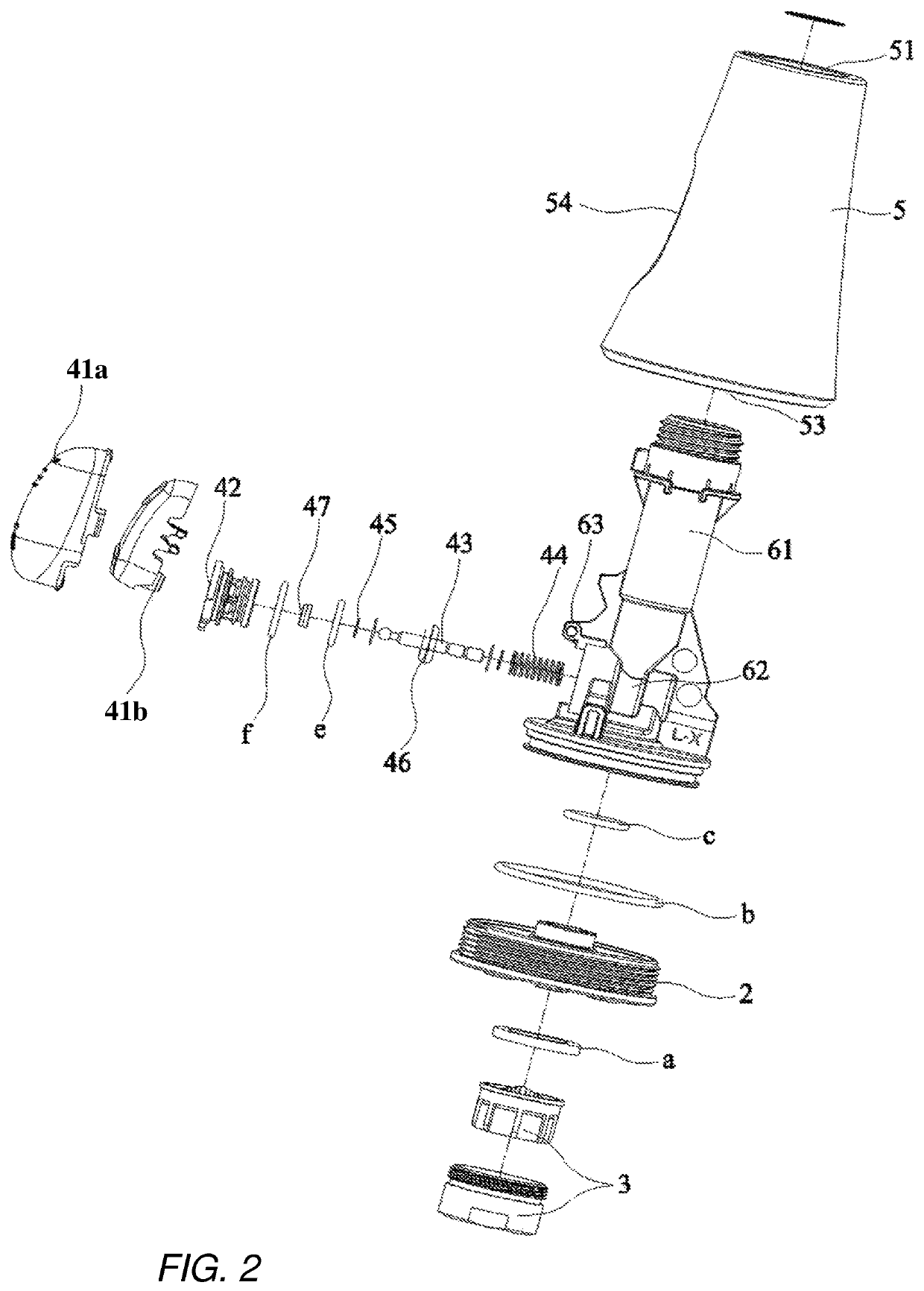
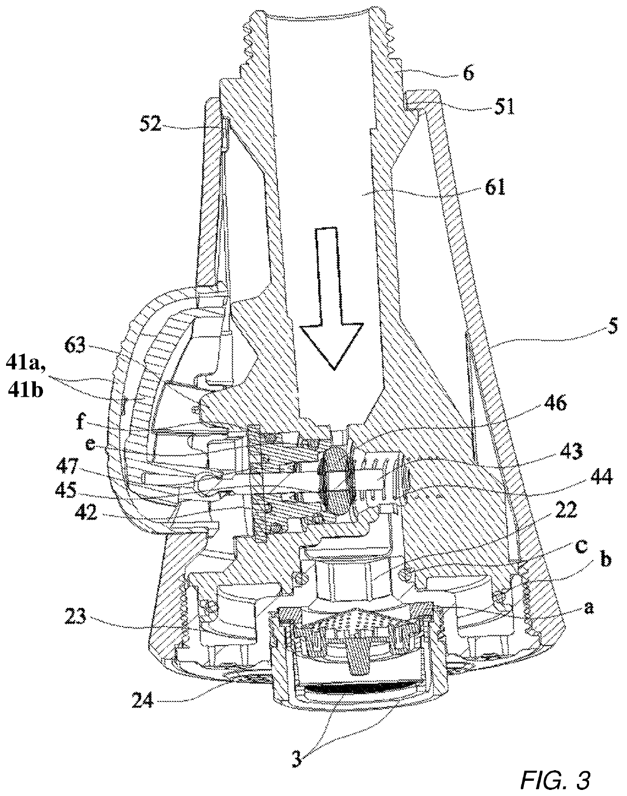
[0024]As shown in FIG. 1 to FIG. 10, the present invention discloses a shower head assembly 10. The shower head assembly 10 comprises a main body 1, a face plate or panel 2, a bubbler component 3 installed in the intermediate portion of the face plate 2, and a switching device 4 installed to the main body 1 for controlling an outflow of discharged water from the face plate 2.

[0025]The center of the front of the face plate 2 has an installation trough 21 (seen in FIG. 4 for example) for installation of the bubbler 3 as shown in FIG. 3. The bubbler 3 is removably connected to the installation trough 21 by a fastener, such as a threaded fastener. In the illustrative embodiment, external threads on the bubbler 3 engage with internal threads of the installation trough 21 for connecting the bubbler 3 with the face plate 2 (see FIGS. 2-5). A sealing ring (a)...


PUM


Abstract

A shower head assembly includes a main body, a face plate, and a switching device installed inside the main body for controlling an outflow of water from the face plate. The circumferential portion of the face plate is provided with a plurality of water outlet units. Each water outlet unit includes a plurality of jet orifices for producing a plurality of fine spouts. Since the diameter of each jet orifice is small, the water discharge force of the fine spouts is stronger. The water-saving effect is good. The shower head can be used for a low water pressure environment.

Description

CROSS-REFERENCE TO RELATED APPLICATIONS[0001]This application is a continuation in part of U.S. patent application Ser. No. 15 / 347,782, filed Nov. 10, 2016, issued as U.S. Pat. No. 10,150,122, the disclosure of which is incorporated in its entirety herein by reference.TECHNICAL FIELD[0002]The present invention relates to a bathroom shower fixture, and more particularly to a shower head structure with multiple units of grouped jet orifices that provide discharged water flow with improved feel.BACKGROUND OF THE INVENTION[0003]With the improvement of people's living standards, people pay more attention to the quality of life and also whether a product is environmentally-friendly and efficient so as to not be wasteful of resources. For taking a shower, people now pay attention to the feeling of the water flow that falls on them during the shower and the water-saving effect. Numerous existing shower heads provide discharged water flow that does not provide physical ease and relaxation, i...

Claims


Application Information

Patent Timeline
Patent Type & Authority Patents(United States)
IPC IPC(8): B05B1/16B05B1/18B05B1/30B05B1/12E03C1/04B05B12/00B05B15/40
CPCB05B1/1609B05B1/12B05B1/1618B05B1/1681B05B1/185B05B1/3013B05B12/002E03C1/04B05B15/40
Inventor WANG, XUEDONGZHANG, JIANGCHENGWU, YUZHENG
Owner XIAMEN LOTA INT CO LTD
Learn More