Interferometry with an achromatic interferometric superposition of electromagnetic fields

a technology of interferometry and electromagnetic field, applied in the direction of optical radiation measurement, instruments, spectrometry/spectrophotometry/monochromators, etc., can solve the problem of reducing the magnitude, and reducing the detection rang

Active Publication Date: 2022-08-09
MAX PLANCK GESELLSCHAFT ZUR FOERDERUNG DER WISSENSCHAFTEN EV
View PDF11 Cites 0 Cited by
  • Summary
  • Abstract
  • Description
  • Claims
  • Application Information

AI Technical Summary

Benefits of technology

[0032]The objective of the invention is to provide an improved interferometer apparatus, an improved interferometric method, an improved interferometric measurement apparatus and / or an improved interferometric measurement method, using an achromatic interferometric superposition of electromagnetic fields and being capable of avoiding limitations and disadvantages of conventional techniques. In particular, the interferometric techniques are to be capable of an achromatic interferometric superposition, in particular subtraction and / or summation, of electromagnetic fields with a broadband spectrum, in particular with increased extinction capability, sensitivity and / or SNR.SUMMARY OF THE INVENTION

Problems solved by technology

This imposes two main limitations on the smallest detectable signal: Firstly, its magnitude is lower-bound by excess source noise.
Secondly, resolving a small change of a comparatively large signal requires high-dynamic-range detection.
However, all these concepts are either technically complex or not suitable for ultrashort-pulse applications.
However, this technique is restricted to measurements with a tunable narrowband laser, but not suitable for broadband measurements with ultrashort pulses.

Method used


Image

  • Interferometry with an achromatic interferometric superposition of electromagnetic fields
  • Interferometry with an achromatic interferometric superposition of electromagnetic fields
  • Interferometry with an achromatic interferometric superposition of electromagnetic fields

Examples


Embodiment Construction

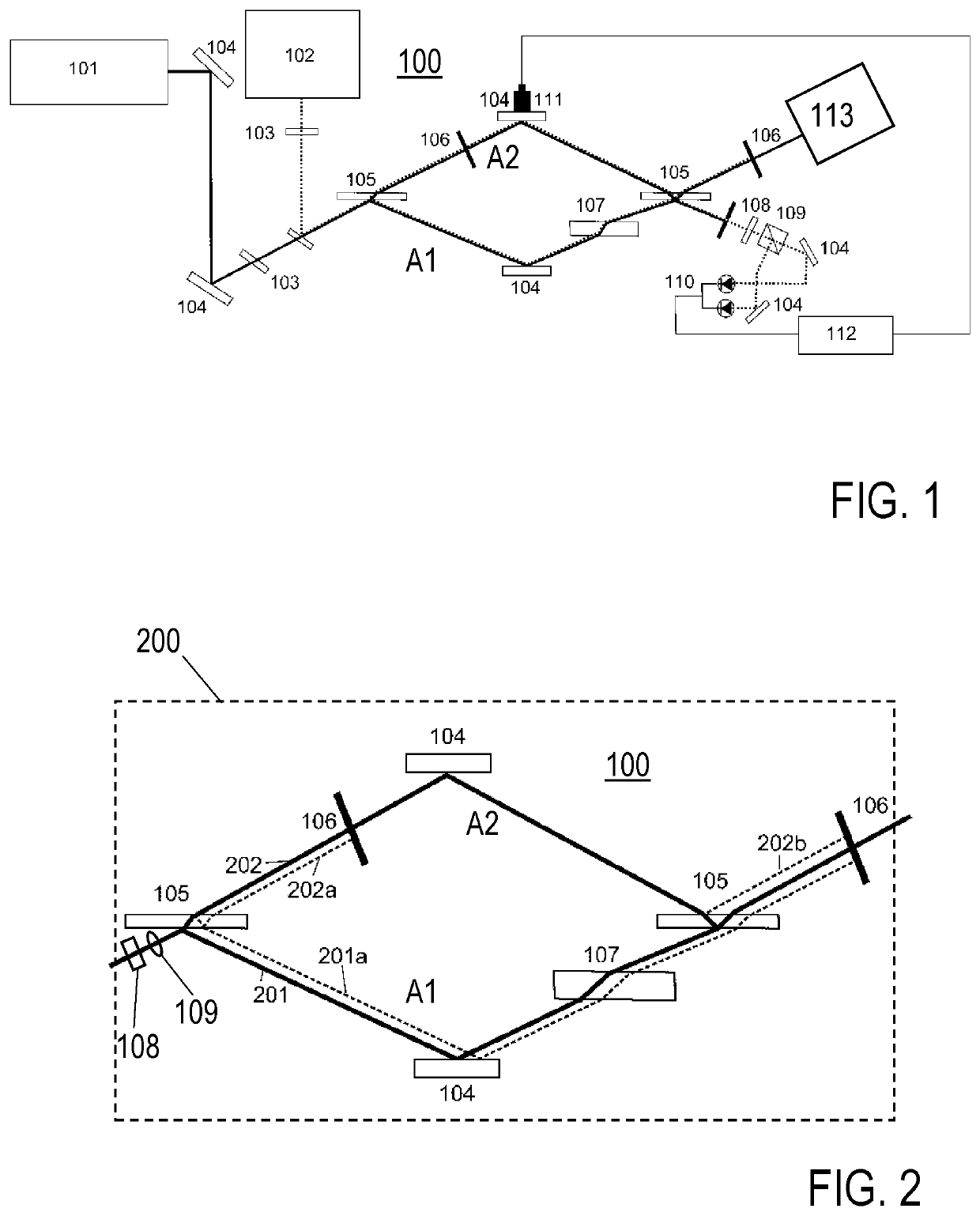
[0061]FIG. 1 shows an embodiment of the inventive interferometer apparatus 100, comprising a broadband laser source 101, an auxiliary laser 102, wire grid polarizers 103, deflection mirrors 104, transparent plates 105, spatial filters 106, a compensating plate (balancing transmission element) 107, a quarter wave plate 108, a polarizing beam splitter 109, a balanced detector 110, a piezo electric transducer 111 for shifting the deflection mirror 104, and locking electronics 112. 113 is a detector device, like a spectrometer or a device for time resolved spectroscopy, for detecting the destructive output of the beam combiner 105. FIG. 2 shows details of the beam path in the interferometer apparatus 100 of FIG. 1, wherein 201 is the first reflection of the beam splitter 105, 201a is a second reflection of beam splitter 105, 202 is a transmission of the beam splitter 105, 202a is a third reflection of beam splitter 105, and 202b is a first reflection of beam combiner 105. Due to the sel...


PUM


Abstract

An interferometer apparatus includes a beam splitter arranged for splitting an input beam into a first beam propagating along a first interferometer arm including a deflection mirror and a second beam propagating along a second interferometer arm including a deflection mirror. The first and second interferometer arms have an identical optical path length. A beam combiner is arranged for recombining the first and second beams into a constructive output and a destructive output. In the first interferometer arm compared with the second interferometer arm, one additional Fresnel reflection at an optically dense medium is provided and a propagation of the electromagnetic fields of the first and second beams, when recombined by the beam combiner, results in a wavelength-independent phase difference of π between the contributions of the two interferometer arms to the destructive output. Furthermore, an interferometric measurement apparatus and an interferometric measurement method are described.

Description

CROSS-REFERENCE TO RELATED APPLICATIONS[0001]This application is a U.S. National Phase Application of PCT / EP2018 / 069229, filed Jul. 16, 2018, the contents of which application are incorporated herein by reference in their entireties for all purposes.FIELD OF THE INVENTION[0002]The invention relates to an interferometer apparatus and to an interferometric method for an achromatic interferometric superposition of electromagnetic fields, in particular utilizing a dual beam path interferometer. Furthermore, the invention relates to an interferometric measurement apparatus and an interferometric measurement method, utilizing the interferometer apparatus and the interferometric measurement apparatus. Applications of the invention are available e. g. in the fields of investigations of radiation-matter interactions, e. g. for measuring spectral responses of samples, spatial distributions of electromagnetic fields and testing optical components.TECHNICAL BACKGROUND[0003]In the present specif...

Claims


Application Information

Patent Timeline
Patent Type & Authority Patents(United States)
IPC IPC(8): G01B9/02G02B27/10
CPCG01B9/02083G02B27/1006G01B2290/65G01B9/02G01J3/4535G01J3/0205G01J3/0224G01J3/0208G01B9/02027G01N21/45
Inventor PUPEZA, IOACHIMKRAUSZ, FERENCBUBERL, THERESA
Owner MAX PLANCK GESELLSCHAFT ZUR FOERDERUNG DER WISSENSCHAFTEN EV
Why Eureka
Try Eureka