Apparatus and methods for particle testing

a particle and apparatus technology, applied in the field of particle testing apparatus, can solve the problems of not accurately determining particle size, affecting the transmission of waveguides, and affecting the accuracy of particle detection results

Pending Publication Date: 2022-05-12
MAX PLANCK GESELLSCHAFT ZUR FOERDERUNG DER WISSENSCHAFTEN EV
View PDF0 Cites 0 Cited by
  • Summary
  • Abstract
  • Description
  • Claims
  • Application Information

AI Technical Summary

Problems solved by technology

As a consequence, this approach can only count the particle number, but not precisely determine the particle size.
However, the following disadvantages may occur in applying the technique of FIG. 6B.
Over prolonged operation the continuous attachment of particles on the tapered waveguide 11′ will severely degrade the transmission of the waveguide 11′ and thus the sensing capability thereof.
Even in the absence of particle attachment, the tapered waveguide will degrade over time.
Therefore the overall lifetime of the device is strictly limited.
However, due to the complex methods of manipulating and sensing the particles, there are substantial restrictions for practical routine applications for investigating e. g. airborne particles.
However, these systems do not allow investigating particles in a gaseous environment, in particular for determining the number or size thereof.

Method used


Image

  • Apparatus and methods for particle testing
  • Apparatus and methods for particle testing
  • Apparatus and methods for particle testing

Examples


Embodiment Construction

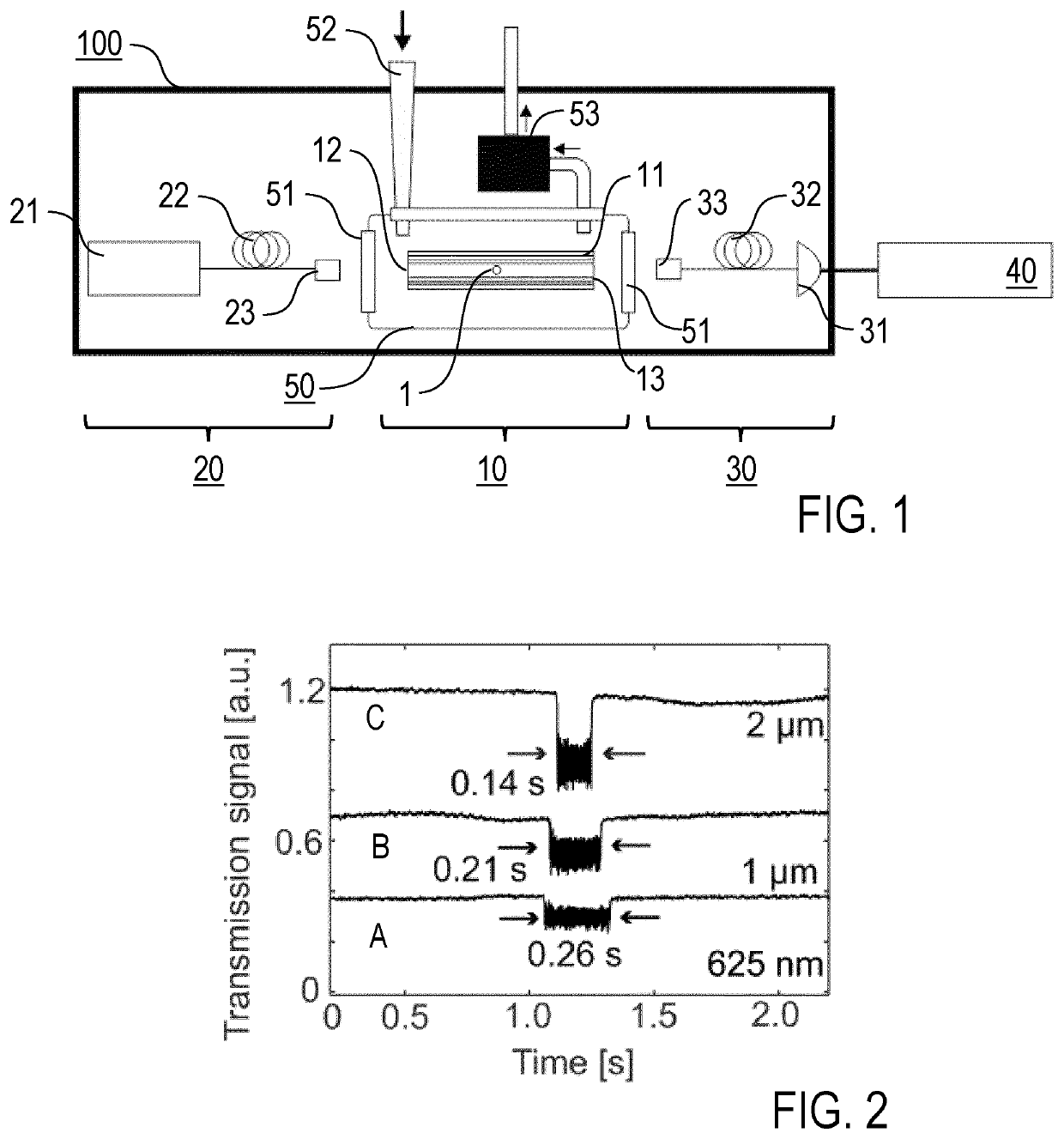
[0052]Embodiments of the invention are described in the following with particular reference to particle testing using a HC-PCF. The invention is not restricted to this embodiment, but can be implemented with other hollow waveguide types, like capillaries, ARROW waveguides. Details of collecting and optionally further preparing the sample to be tested are not described as sample collection and preparation techniques are known per se from conventional analysing techniques. For instance, the sample can be collected by sucking or collecting a portion of air or other reaction gas or sample liquid from an environment or closed space. The invention is adapted for testing samples in a gaseous or liquid condition. In particular, a liquid sample can be tested directly by guiding the liquid sample through the optical waveguide, or by converting it into the gaseous condition while keeping possible particles within the sample, e.g. using a medical nebulizer.

[0053]A single channel embodiment of t...


PUM

PropertyMeasurementUnit
core diameteraaaaaaaaaa
NIR wavelengthaaaaaaaaaa

Abstract

A particle testing apparatus, being configured for investigating particles in a fluid medium, includes a waveguide device having a hollow optical waveguide with an input end and an output end, an irradiation device including a laser source being arranged for optically trapping at least one particle at the input end of the optical waveguide and propelling the particle through the optical waveguide toward the output end thereof, and a measuring device being arranged for sensing the at least one particle in the optical waveguide, wherein the measuring device is arranged for measuring an optical transmission of the optical waveguide. Furthermore, a particle testing apparatus is described.

Description

FIELD OF THE INVENTION[0001]The invention relates to a particle testing apparatus for investigating particles in a fluid medium, e. g. a gaseous or liquid environment, in particular employing a detection of particles propelled in a hollow gas- or liquid-filled optical waveguide. Furthermore, the invention relates to a particle testing method for investigating particles in a fluid medium. Applications of the invention are available e. g. in the fields of environmental or material investigations or monitoring chemical or physical processes.TECHNICAL BACKGROUND[0002]In the present specification, reference is made to the following prior art illustrating technical background of the invention and related techniques:[0003][1] R. S. Gao et al. in “Aerosol Science and Technology” 47, 137-145 (2013);[0004][2] Met One Instruments: https: / / metone.com / indoor-controlled-environments / controlled-environments / model-804-handheld-particle-counter / ;[0005][3] X.-C. Yu et al. in “Light: Science & Applica...

Claims


Application Information

Patent Timeline
Patent Type & Authority Applications(United States)
IPC IPC(8): G01N15/02G01N1/22G01N15/14
CPCG01N15/0211G01N1/2273G01N2015/0046G01N15/1434G01N15/1459G01N2015/0038G01N2015/1493
Inventor RUSSELL, PHILIPZELTNER, RICHARDXIE, SHANGRANSHARMA, ABHINAV
Owner MAX PLANCK GESELLSCHAFT ZUR FOERDERUNG DER WISSENSCHAFTEN EV
Why Eureka
Try Eureka