Pulse light source device and method for creating CEP stable fs laser pulses

a pulse light source and pulse technology, applied in the field of pulse light source devices, can solve the problems of difficult direct cep stable sc generation from 1-ps pulses, difficult attosecond-pump, near-inability to perform attosecond-probe spectroscopy, etc., and achieve the effect of improving the efficiency of the opcpa process and improving the output power of the fs output pulses

Active Publication Date: 2019-12-31
MAX PLANCK GESELLSCHAFT ZUR FOERDERUNG DER WISSENSCHAFTEN EV +1
View PDF9 Cites 1 Cited by
  • Summary
  • Abstract
  • Description
  • Claims
  • Application Information

AI Technical Summary

Benefits of technology

[0037]The objectives of the invention are to provide an improved pulse light source device and an improved method for creating fs pulses, which are capable of avoiding limitations and disadvantages of conventional techniques, resp. In particular, the device and method are to be capable to provide an extended spectral coverage of fs pulse generation and / or improved flexibility in adjusting the spectral intensity characteristic of the fs pulses.SUMMARY OF THE INVENTION

Problems solved by technology

However the limited flux of the attosecond pulses of the current technology makes attosecond-pump, attosecond-probe spectroscopy nearly impossible and calls for sources with higher photon flux [4].
However, direct CEP stable SC generation from 1-ps pulses has been challenging so far.
The active control has disadvantages in terms of complexity, reliability and stability.
This technique has disadvantages as the pump source is restricted to create short pulses with a duration below 500 fs, so that the bandwidth of the generated pulses is restricted.
This approach limits the achieved CEP-stable pulses to a narrow wavelength range only, so that the technique of [23] can have limitations in terms of restricting the SC generation to the driving with an idler beam having a fixed central wavelength.

Method used


Image

  • Pulse light source device and method for creating CEP stable fs laser pulses
  • Pulse light source device and method for creating CEP stable fs laser pulses

Examples


Embodiment Construction

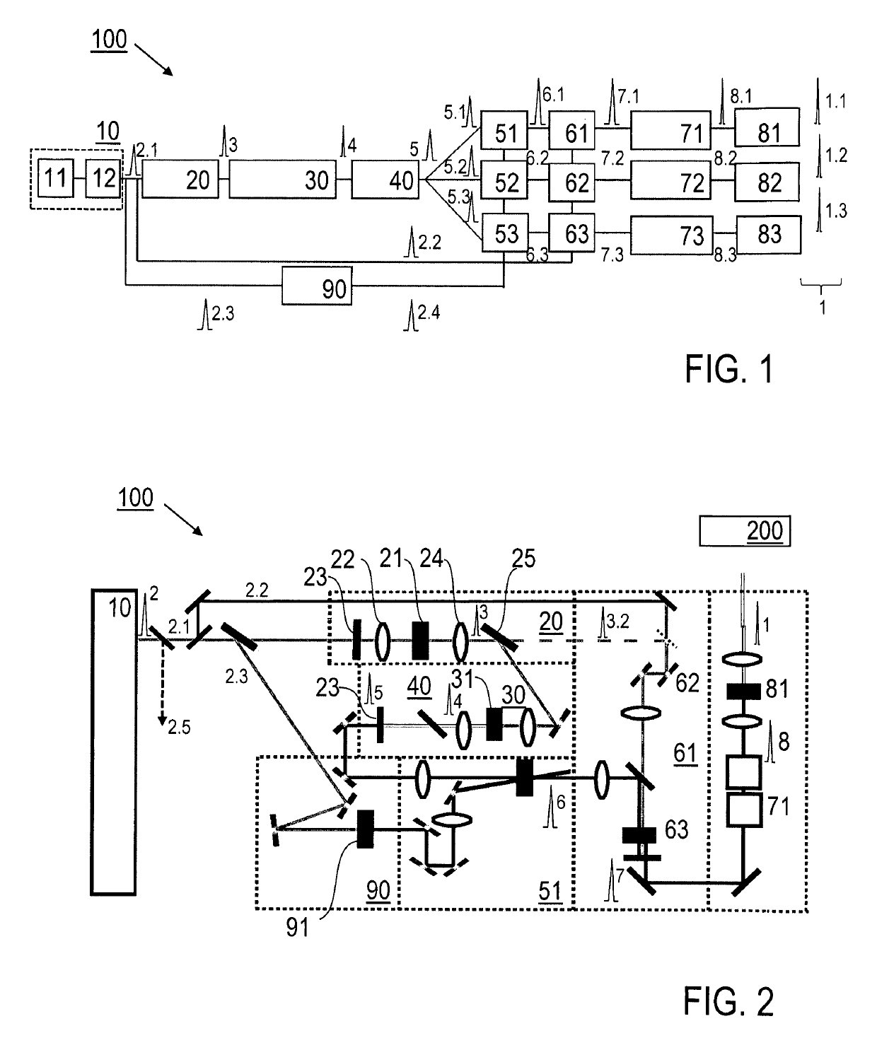
[0069]Features of preferred embodiments of the invention are described in the following with particular reference to the combination of the components of the pulse source device and the operation thereof. These components, in particular the ps pulse source device, the frequency shifting device, the pulse shortening device, the primary supercontinuum generation device, the pulse stretcher device, the first and optionally further OPCPA device(s), the first and optionally further phase stabilization device(s), the first and optionally further pulse compressor device(s), and the first and optionally further secondary supercontinuum generation device(s) are schematically illustrated in FIG. 1. Details of these components are described in an exemplary manner with reference to FIG. 2, but can be modified as far as they are known as such from conventional light pulse generation, pulse manipulation and light amplification techniques. With a practical implementation of the invention, these co...


PUM


Abstract

A pulse light source device (100) for creating fs output laser pulses (1, 1.1, 1.2, 1.3) having CEP stability comprises a pulse source device (10) creating primary ps laser pulses, a first beam splitting device (13) splitting the primary ps laser pulses to first ps laser pulses (2.1) and second ps laser pulses (2.2), a pulse shortening device (20) creating sub-ps laser pulses (3) by shortening and spectrally broadening the first ps laser pulses (2.1), a primary supercontinuum generation device (30) creating primary fs laser pulses (4), a pulse stretcher device (40) creating stretched ps laser pulses (5, 5.1) by stretching the primary fs laser pulses (4), a optical parametric chirped-pulse amplification device (51) creating amplified ps laser pulses (6, 6.1) on the basis of the stretched ps laser pulses (5, 5.1) and the second ps laser pulses (2.2); a phase stabilization device (61) creating CEP stable ps laser pulses (7, 7.1) by difference frequency generation of the amplified ps laser pulses (6, 6.1) and reference laser pulses derived from the primary ps laser pulses (2) or the sub-ps laser pulses (3), a pulse compressor device (71) creating compressed fs laser pulses (8, 8.1) by compressing the CEP stable ps laser pulses (7, 7.1) output by the phase stabilization device (61), and a secondary supercontinuum generation device (81) creating fs output laser pulses as the fs output laser pulses (1, 1.1) to be obtained by spectrally broadening the compressed fs laser pulses (8, 8.1). Furthermore, a method of creating fs output laser pulses is described.

Description

CROSS REFERENCE TO RELATED APPLICATIONS[0001]This application is the U.S. National Phase Application of PCT / EP2016 / 000965, filed Jun. 10, 2016, the contents of which is incorporated herein by reference in its entirety for all purposes.TECHNICAL FIELD[0002]The invention relates to a pulse light source device and a method for creating femtosecond (fs) output laser pulses having carrier-envelope-phase (CEP) stability. In particular, the invention relates to a CEP-stable fs pulsed light source and an operating method thereof. Applications of the invention are available e. g. in the fields of generating seeding pulses for pulse amplifiers, like OPAs or OPCPAs, generating of ultrashort, high energy pulses for laboratory use in science, such as in attosecond (as) science, generating high harmonic radiation, generating seeding pulses for seeding of optical waveform synthesizers, and / or time-resolved spectroscopy.TECHNICAL BACKGROUND[0003]For describing the background of the invention, parti...

Claims


Application Information

Patent Timeline
Patent Type & Authority Patents(United States)
IPC IPC(8): H01S3/13H01S3/00H01S3/06H01S3/23H01S3/16
CPCH01S3/0078H01S3/0604H01S3/0057H01S3/1307H01S3/0092H01S3/2383H01S3/1643H01S3/16H01S3/1618G02F1/39G02F2203/26G02F1/392H01S3/005H01S2301/08
Inventor KRAUSZ, FERENCFATTAHI, HANIEH
Owner MAX PLANCK GESELLSCHAFT ZUR FOERDERUNG DER WISSENSCHAFTEN EV
Why Eureka
Try Eureka