Dust suction device utilizing beads

a technology of dust suction device and ball, which is applied in lighting and heating apparatus, ventilation systems, heating types, etc., can solve the problems of not achieving a long life span, and achieve the effect of maximizing durability and cleaning of products and easy breaking

Active Publication Date: 2022-09-06
TESTONIC
View PDF9 Cites 0 Cited by
  • Summary
  • Abstract
  • Description
  • Claims
  • Application Information

AI Technical Summary

Benefits of technology

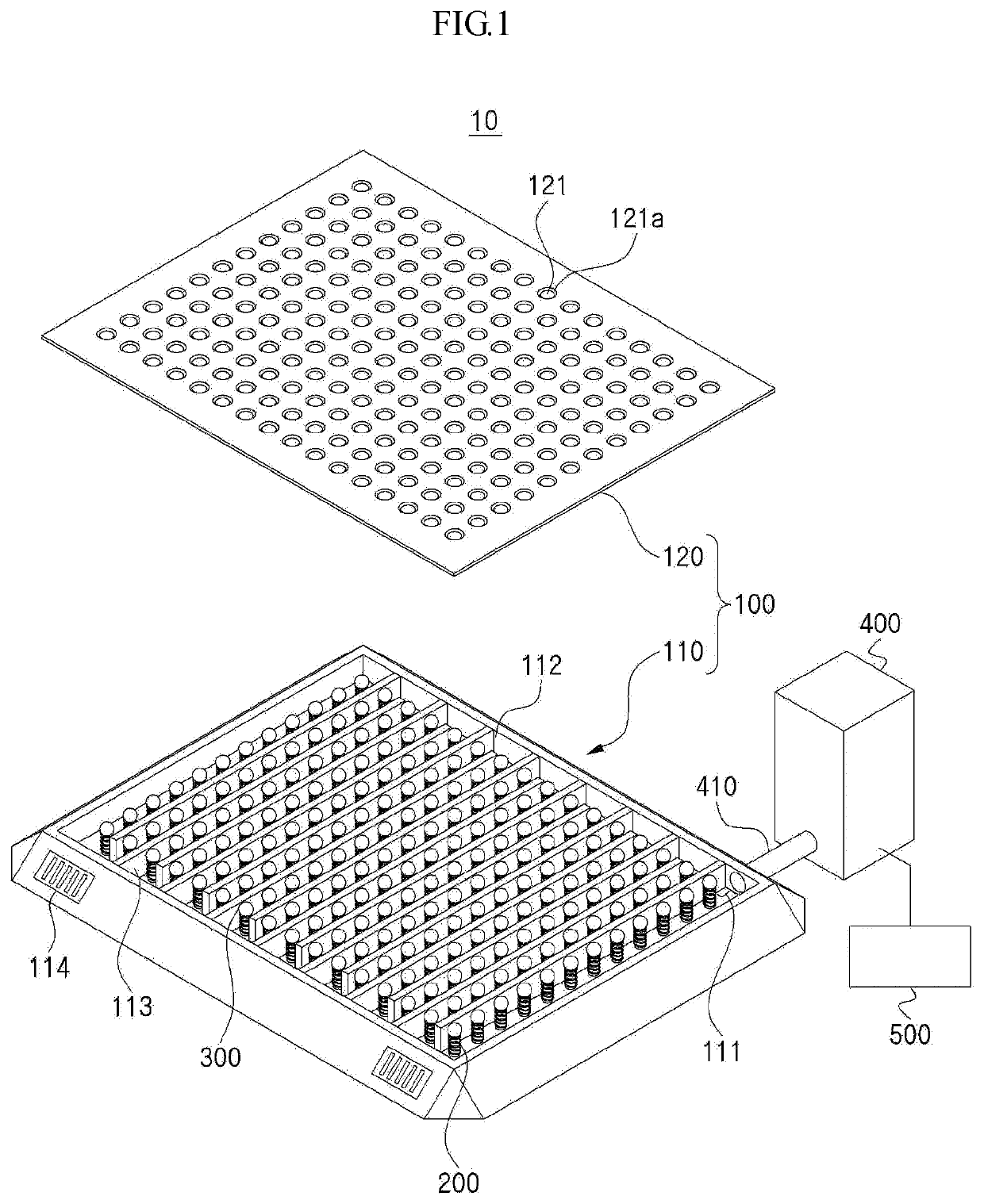
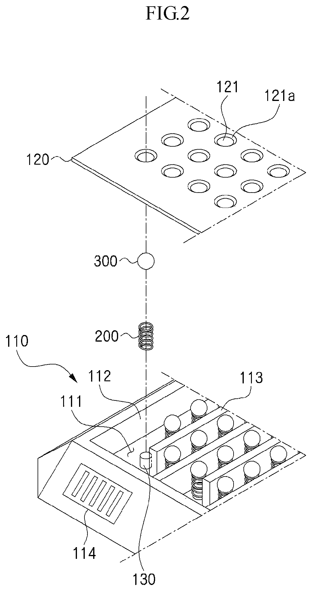
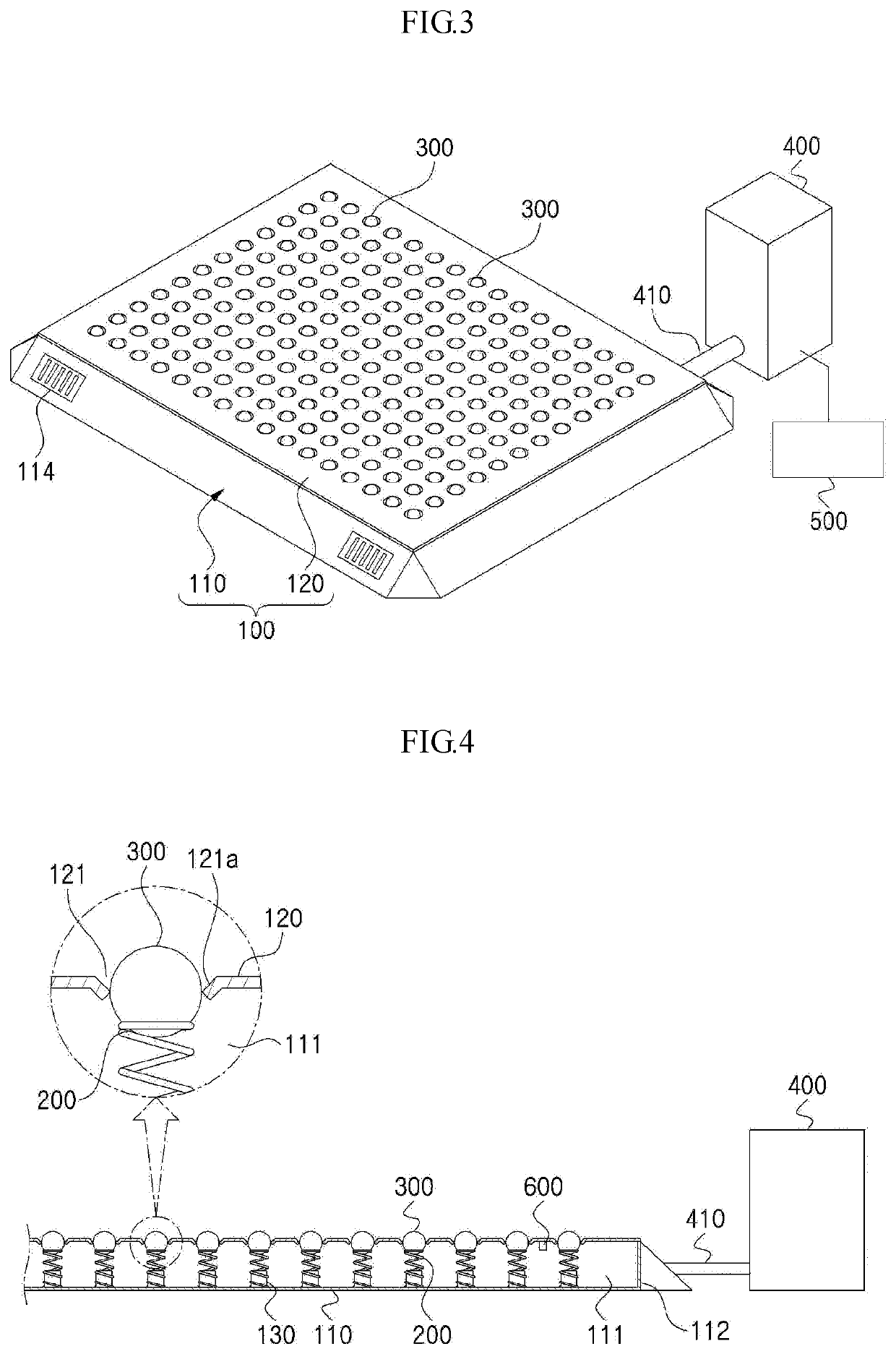
[0020]According to the present invention, the dust suction device is provided with the balls disposed on tops of the springs to open and close the suction holes formed on the footboard of the main body, so that in a state where portions of top peripheries of the balls are protruding upwardly from the suction holes in such a manner as to close the suction holes, if the balls protruding from the footboard are stepped by the shoes, they are moved down, while being supported elastically against the springs, and at this time, since the balls are spherical, they are gently moved down to open the suction holes, without being locked onto the side peripheries of the suction holes, thereby maximizing a removal efficiency for the foreign matters like dust, soil and so on.
[0021]In addition, the dust suction device according to the present invention is provided with the balls supported elastically against the springs under the suction holes of the footboard, so that as the balls are made of stainless steel or carbon or chrome steel coated with nickel, they are not easily broken even at the application of strong impacts thereto and prevent dust from sticking thereto, thereby maximizing durability and cleanness of a product.

Problems solved by technology

According to the Patent document 1, if the head blocks exposed to the outside are stepped by a person with access, they are descended to open the suction holes, and since they are made of a plastic material, however, they may be broken due to his or her weight or other environmental factors at the time when they are stepped, thereby failing to achieve a long life span.

Method used


Image

  • Dust suction device utilizing beads
  • Dust suction device utilizing beads
  • Dust suction device utilizing beads

Examples


Embodiment Construction

[0027]The present invention may be modified in various ways and may have several exemplary embodiments. Specific exemplary embodiments of the present invention are illustrated in the drawings and described in detail in the detailed description. However, this does not limit the invention within specific embodiments and it should be understood that the invention covers all the modifications, equivalents, and replacements within the idea and technical scope of the invention.

[0028]In the description, the thicknesses of the lines or the sizes of the components shown in the drawing may be magnified for the clarity and convenience of the description. Further, the terms as will be discussed later are defined in accordance with the functions of the present invention, but may be varied under the intention or regulation of a user or operator. Therefore, they should be defined on the basis of the whole scope of the present invention.

[0029]In the description, a term ‘and / or’ includes a combinati...


PUM


Abstract

A dust suction device includes: a main body composed of a bottom plate and a footboard, wherein a dust suction part is formed in the bottom plate, and the footboard seals the dust suction part and has suction holes formed on the upper part thereof to allow the dust to be sucked to the dust suction part; a number of springs provided on the bottom inside the bottom plate matching the number of suction holes; balls which are provided on the upper part of the springs and which are in close contact with the suction holes of the footboard and open and close the suction holes; and a suction part which is connected to a side portion of the main body through a hose and sucks the dust through the suction holes toward the dust suction part when the suction holes are open.

Description

CROSS-REFERENCE TO RELATED APPLICATIONS[0001]The present application is a U.S. National Phase entry from International Application No. PCT / KR2018 / 004187, filed Apr. 10, 2018, which claims priority to Korean Patent Application No. 10-2017-0047694, filed Apr. 13, 2017, the disclosures of which are incorporated by reference herein in their entirety.BACKGROUND1. Technical Field[0002]The present invention relates to a dust suction device using balls, and more particularly, to a dust suction device that is provided with balls supported against springs under suction holes formed on a footboard, so that the balls are moved up and down to open and close the suction holes, while being supported against the springs, thereby achieving gentle dust suction, preventing breakage of the dust suction device, and suppressing foreign matters from sticking to the balls.2. Description of Related Art[0003]In facilities, such as factories, hospitals, and stores, generally, dust attached to shoes of a perso...

Claims


Application Information

Patent Timeline
Patent Type & Authority Patents(United States)
IPC IPC(8): A47L23/00A47L9/00A47L23/26B08B5/04F24F7/10F24F11/00A47L23/02
CPCA47L9/0072A47L23/02A47L23/263A47L23/266B08B5/04F24F7/10F24F11/0001A47L23/22Y02A50/2351F24F8/00
Inventor SHIN, WON CHUL
Owner TESTONIC
Why Eureka
Try Eureka