Clip

a technology of clip and paper, applied in the field of clip, can solve the problems of clip itself or some paper pieces being liable to move and slip off with a slight external force, clip is liable to come off, and the gripping force of paper pieces is not particularly applied, so as to achieve a large resistance to tensile force, strong gripping force, and less prone to come off.

Active Publication Date: 2022-09-06
ISHIDA HIROTOSHI
View PDF28 Cites 0 Cited by
  • Summary
  • Abstract
  • Description
  • Claims
  • Application Information

AI Technical Summary

Benefits of technology

[0006]This disclosure has been made in view of the circumstances described above, and has an object to provide a clip that is less liable to come off after holding a folded portion formed by folding a corner of a stack of a plurality of paper pieces and is advantageous in terms of cost.
[0011]According to the at least one embodiment of this disclosure, the paper piece portion on the front side and the paper piece portion on the back side with respect to the valley are clamped between the front-side clamping piece and the insertion piece and between the insertion piece and the back-side clamping piece, respectively. At the same time, both of the paper piece portion on the front side and the paper piece portion on the back side are clamped between the front-side clamping piece and the back-side clamping piece. Thus, the clip has a generally strong gripping force, and thus is less liable to come off. Further, the insertion piece is inserted and placed in the valley. Thus, the clip has large resistance against a tensile force acting on the paper pieces. Thus, at the time of manufacture of the clip, use of a low-strength material and reduction in thickness are enabled. Further, because the insertion piece, the front-side clamping piece, and the back-side clamping piece are elastically and integrally formed, the gripping force is generated. Thus, such formation of the clip contributes to reduction in cost. Still further, the clip is attached and removed by using elasticity of the clip. Thus, attachment and removal work is easily performed.
[0012]According to the at least another embodiment of this disclosure, the clip is formed with a simple structure, and the simple structure contributes to further reduction in cost.
[0013]According to the at least another embodiment of this disclosure, when the paper pieces are inserted, the paper pieces are brought into contact with and pressurized between the insertion piece and the front-side clamping piece or are brought into contact with and pressurized between the insertion piece and the back-side clamping piece at the crossing portion. Thus, the gripping force of the clip is increased. As a result, the clip is much less liable to come off. Further, the increase in gripping force is achieved with a simple structure in which the crossing portion is additionally formed. Thus, the clip is reasonable.
[0014]According to the at least another embodiment of this disclosure, the clip has a simple structure, and the simple structure contributes to further reduction in cost.

Problems solved by technology

However, the Gem clip has a disadvantage in that the clip itself or some of the paper pieces are liable to move and slip off with a slight external force.
However, a gripping force for paper pieces is not particularly applied between the insertion piece and the front-side clamping piece or between the front-side clamping piece and the back-side clamping piece.
Thus, a gripping force is generally weak, and thus there still arises a problem in that the clip is liable to come off.
S56-163565 is inevitably increased in cost because the insertion piece, the front-side clamping piece, and the back-side clamping piece are formed continuously so as to be foldable.
Further, the clip is inevitably increased in cost also because the magnetic attraction members are used.

Method used


Image

  • Clip
  • Clip
  • Clip

Examples


Embodiment Construction

[0027]Embodiments of this disclosure are now described with reference to the accompanying drawings.

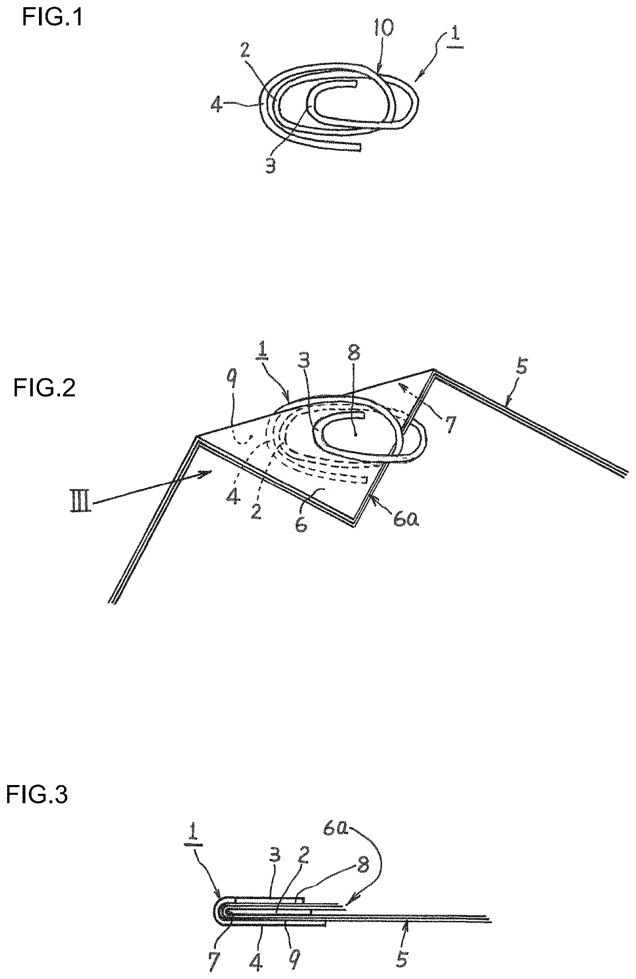
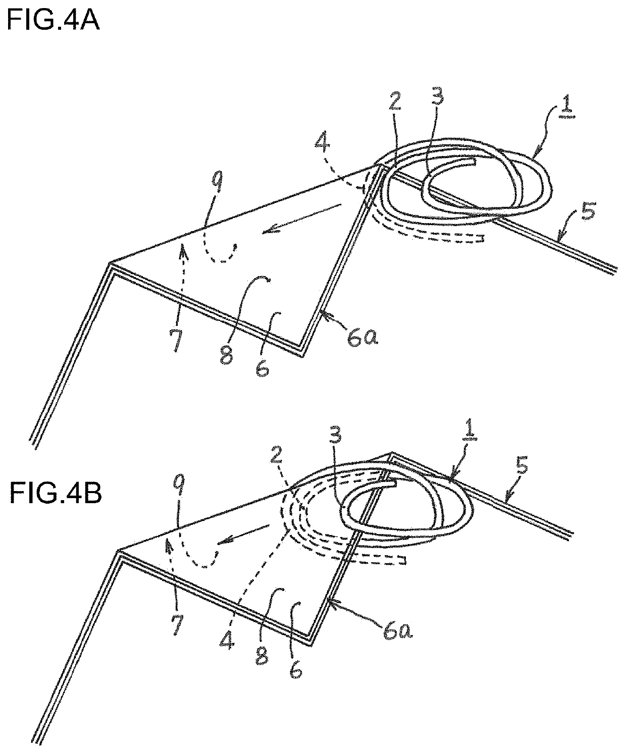
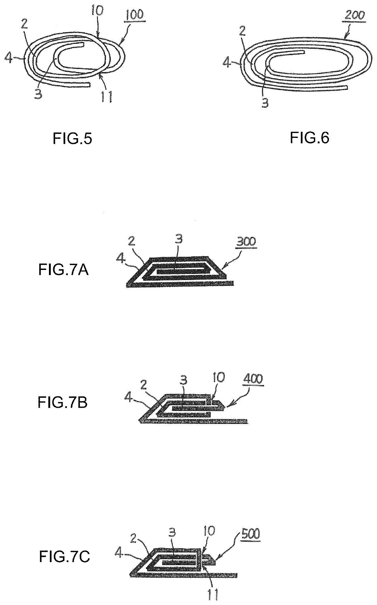
[0028]As illustrated in FIG. 1, a clip 1 according to at least one embodiment of this disclosure includes an insertion piece 2, a front-side clamping piece 3, and a back-side clamping piece 4. The insertion piece 2, the front-side clamping piece 3, and the back-side clamping piece 4 are elastically and integrally formed. As illustrated in FIG. 2 and FIG. 3, the insertion piece 2 is inserted into a valley 7 defined by forming a folded portion 6a. The folded portion 6a is formed by folding a corner 6 of a stack of a plurality of paper pieces 5. Under the inserted state, the front-side clamping piece 3 and the back-side clamping piece 4 are in contact with a paper piece portion 8 on a front side and a paper piece portion 9 on a back side with respect to the valley 7. Owing to elasticity of the clip 1, the paper piece portion 8 on the front side and the paper piece portion 9 on the back si...


PUM


Abstract

A clip includes an insertion piece insertable into a valley formed by folding a corner of a stack of a plurality of paper pieces, a front-side clamping piece contactable with a paper piece portion on a front side of the valley, and a back-side clamping piece contactable with a paper piece portion on a back side of the valley. The insertion piece, front-side clamping piece, and back-side clamping piece are elastically and integrally formed so that the paper piece portion on the front side and the paper piece portion on the back side of the valley are clamped between the front-side clamping piece and the insertion piece and between the insertion piece and the back-side clamping piece, respectively, and both of the paper piece portion on the front side and the paper piece portion on the back side of the valley are clamped between the front-side and back-side clamping pieces.

Description

RELATED APPLICATIONS[0001]The present application is a National Phase of International Application No. PCT / JP2019 / 032764 filed Aug. 22, 2019, which claims priority to Japanese Application No. 2018-158417, filed Aug. 27, 2018.BACKGROUNDTechnical Field[0002]This disclosure relates to a clip configured to hold and fasten a folded portion formed by folding a corner of a stack of a plurality of paper pieces.Background Art[0003]As an example of a clip configured to hold and fasten a plurality of paper pieces together, there has been known a clip called “Gem clip” which is formed by bending a wire to an elongated spiral shape. The Gem clip is inexpensive because of its simple structure. However, the Gem clip has a disadvantage in that the clip itself or some of the paper pieces are liable to move and slip off with a slight external force.[0004]Thus, as a clip without the disadvantage described above, the following clip has been proposed in Japanese Utility Model Publication Laid-open No. S...

Claims


Application Information

Patent Timeline
Patent Type & Authority Patents(United States)
IPC IPC(8): B42F1/12
CPCB42F1/12B42F1/08B42F1/10
Inventor ISHIDA, HIROTOSHI
Owner ISHIDA HIROTOSHI
Why Eureka
Try Eureka