Apparatus and methods for remote measurement of sea surface temperature

a technology of remote measurement and sea surface temperature, applied in the direction of measurement devices, instruments, optical radiation measurement, etc., can solve the problems of inaccurate measurement of sea surface skin temperature, deficiency in some aspects, and rise in sea surface temperatur

Active Publication Date: 2022-09-13
SOLHEIM FREDRICK S
View PDF7 Cites 4 Cited by
  • Summary
  • Abstract
  • Description
  • Claims
  • Application Information

AI Technical Summary

Benefits of technology

[0011]The apparatus and methods of this invention overcome the deficiencies of currently utilized methods of measuring sea surface (skin) temperature. The methods and apparatus accurately remotely (from the deck railing of a ship, for instance) determine the sea surface temperature utilizing a compact automatic (thus unattended) marine-worthy system. This invention largely overcomes the error and bias of current sea surface temperature remote measurements.
[0012]The instant apparatus and methods provide the capability for rapid capture of measurements in a plurality of pixels whose field-of-view (FOV) widths are a fraction of a degree, spanning only a few millimeters of wave surface. Thus, pixels each view in a wave across a very small and nearly constant or flat portion of the wave surface, and therefore sample a single thermal value of upwelling fluxes. In this way the pixel(s) are minimally contaminated with sky flux reflection to be determined, and the emission from the sea and the reflected flux from the sky can be more accurately known and corrected for to allow determination of the blackbody temperature of the sea surface.
[0013]The apparatus includes a closely calibrated passive noncontact infrared thermal 8 to 14 micron band multi-pixel camera capable of capturing a plurality of pixels in each captured image of its field of view. These thermal bands are well suited for this measurement, as the emissions come from approximately the first 10 microns of sea surface depth, making it a true sea surface skin temperature measurement. While any infrared thermal band could be used provided it measures thermal emission, the 8 to 14 micron band is optimum because of availability of highly resolute and accurate low cost cameras and minimal contamination of intervening atmosphere. The camera is calibrated to express the thermal blackbody temperature of each of the pixels. The methods of this invention include directing the field of view of the camera to the ocean surface at a known incidence angle. The majority of the received thermal flux is emitted from the first several microns of the sea surface “skin” and is the sea surface temperature. A component of the received thermal radiation is a variable flux from sky reflected from the varying wave surface angles in the field of view. The flux emitted from the sea surface and the reflected sky flux in each pixel are dependent upon the angle of the wave surface viewed in each pixel, the “look” angle of the of the infrared camera onto the wave surface in each pixel, and angle of the reflected view of the sky in each pixel. These angles are known by the elevation angle of the infrared camera and the so-called Fresnel's Equations that define angles of emission and reflection across a dielectric interface.

Problems solved by technology

Much of the heat trapped by increasing atmospheric greenhouse gas levels is emitted and absorbed by the ocean, causing ocean temperatures to rise.
Each has its advantages, but all remain deficient in some regards.
In particular, many heretofore known measurement systems typically measure below the sea surface and are thus not accurate measures of sea surface skin temperature.
This same deficiency applies also to satellite sea surface temperature measurements where the large variation in sea slope and unknown sea state, and their emission and reflection in the wide footprint of the satellite instrument, bias the sea surface temperature measurement by unknown amounts.
Sufficiently accurate sea surface temperature cannot therefore be extracted from such observations.
The resultant measurement of the current methods can be in error by many degrees in temperature, whereas needed accuracy for different applications is often as definitive as 0.1 C.

Method used


Image

  • Apparatus and methods for remote measurement of sea surface temperature
  • Apparatus and methods for remote measurement of sea surface temperature
  • Apparatus and methods for remote measurement of sea surface temperature

Examples


Embodiment Construction

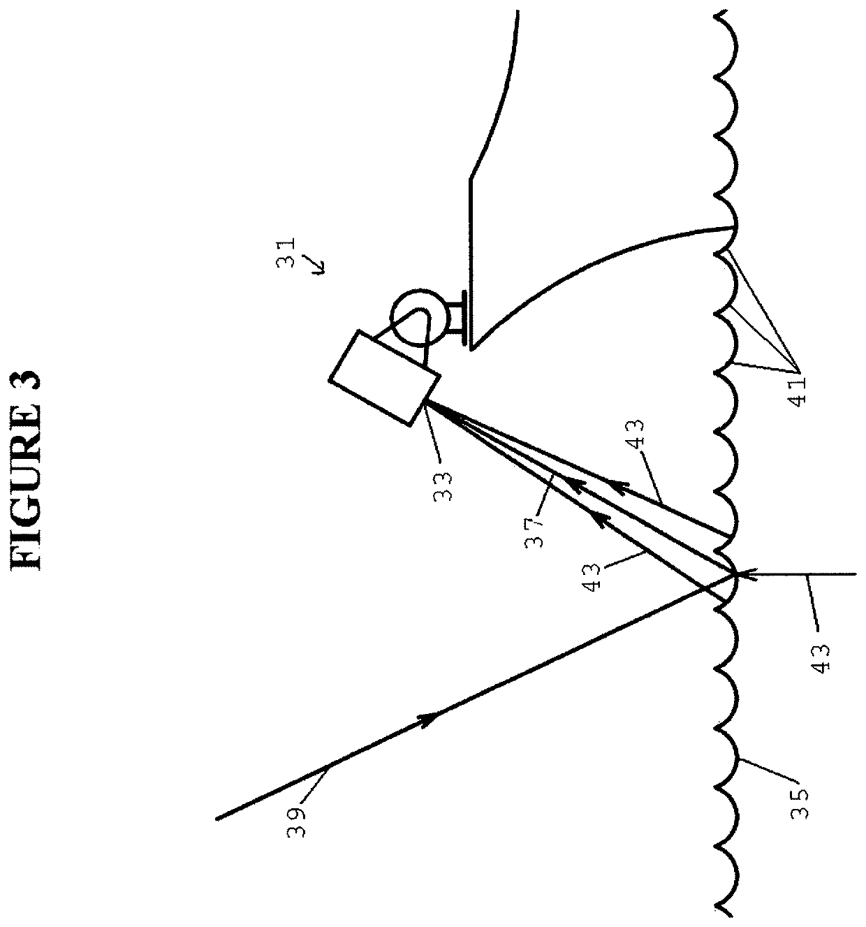
[0052]FIG. 3 depicts the sea-viewing measurement apparatus of this invention. Infrared camera system 31 is preferably located on a suitable location of a sea going vessel or structure. In use on ships, the bow area is preferred location to observe the sea surface undisturbed by the motion of the ship that stirs and mixes the water. Camera 33 is pointed downward to sea surface 35 to capture an image of the surface. The camera pixels are calibrated in equivalent blackbody temperature of the received flux. This flux includes a small contribution from reflected flux 37 from downwelling sky radiation 39. The pixels in the image originate from varying slopes of the waves 41 on the sea surface, and contain differing amounts of upwelling emission from the sea 43 and the reflected sky flux 37 contribution, as defined by Fresnel's Equations.

[0053]FIG. 4 illustrates data indicative of reflections from sea water for orthogonal polarizations in the plane of (45) and perpendicular to the plane of...


PUM


Abstract

Apparatus and methods are disclosed for highly accurate remote measurement of sea surface skin temperature. Thermal band 8 to 14 micron images of the surface of the ocean taken by a downward looking infrared camera are processed to determine the optimum segments of the image to utilize. The influence of contaminating reflection of the downwelling flux from the sky and other error sources are removed and from the data and / or otherwise corrected for making sea surface temperature accuracy within several tenths of a degree possible.

Description

GOVERNMENT SUPPORT[0001]This invention was made with U.S. government support under contracts N00014-16-P3028 and N6833518 C0261 awarded by the United States Navy. The government has certain rights in the invention.FIELD OF THE INVENTION[0002]This invention relates to oceanographic and atmospheric temperature sensing and measurement, and, more particularly, relates apparatus and methods for sea surface temperature measurement.BACKGROUND OF THE INVENTION[0003]Sea surface (also known as sea surface skin) temperature provides fundamental information on the global climate system and ocean circulations. Because it affects the uptake of water into the atmosphere, sea surface temperature is an essential parameter in weather prediction and atmospheric model simulations of weather and climate patterns across the globe. Ocean circulations such as El Nino, La Nina and such circulations of all scales manifest in sea surface temperature features due to upwelling and sinking flows. Much of the hea...

Claims


Application Information

Patent Timeline
Patent Type & Authority Patents(United States)
IPC IPC(8): G01J5/06G01J5/00G01J5/02G01J5/07G01J5/80G01J5/04G01J5/068
CPCG01J5/06G01J5/007G01J5/0037G01J5/0275G01J5/047G01J5/07G01J5/804G01J5/068G01J5/04G01J2005/0077G01J5/0816G01J5/0802G01J5/80G01J5/53
Inventor SOLHEIM, FREDRICK S.
Owner SOLHEIM FREDRICK S
Why Eureka
Try Eureka