Terminal block with integral guiding structure

a technology of integral guiding structure and terminal block, which is applied in the direction of coupling contact member, coupling device connection, electrical apparatus, etc., can solve the problems of permanent deformation of elastic strip and lack and achieve the effect of increasing practicality and reducing the amount of elastic clamping for

Active Publication Date: 2022-09-13
DINKLE ENTERPRISE CO LTD +1
View PDF10 Cites 0 Cited by
  • Summary
  • Abstract
  • Description
  • Claims
  • Application Information

AI Technical Summary

Benefits of technology

[0005]An object of the disclosure is to provide a terminal block with an elastic strip facilitating assembly, which makes the elastic strip be assembled in the insulative base without being bent to excessive angle to keep the elastic clamping force.
[0007]In comparison with related art, the guiding structure of the terminal block of the disclosure includes a guiding plate and a guiding arm. A passing space is formed between the insulative base and a top of the guiding plate facing the insertion hole. An L-shaped space is formed between two adjacent sides of the guiding plate and the insulative base. A U-shaped space is formed between two adjacent sides of the guiding arm and the insulative base. As a result, when the elastic strip is being assembled to the U-shaped space, the abutting section may be inserted to the passing space first and then the U-shaped section is placed around the annular bar of the guiding structure and the positioning section is pressed to be disposed in the U-shaped space. Thus, the elastic strip may be assembled in the insulative base without being bent to excessive angle. Thus, the elastic clamping force may be kept and the practicality may be increased.

Problems solved by technology

Thus, the elastic strip may have the issue of permanent deformation and lacking elastic clamping force.

Method used


Image

  • Terminal block with integral guiding structure
  • Terminal block with integral guiding structure
  • Terminal block with integral guiding structure

Examples


Embodiment Construction

[0013]The technical contents of this disclosure will become apparent with the detailed description of embodiments accompanied with the illustration of related drawings as follows. It is intended that the embodiments and drawings disclosed herein are to be considered illustrative rather than restrictive.

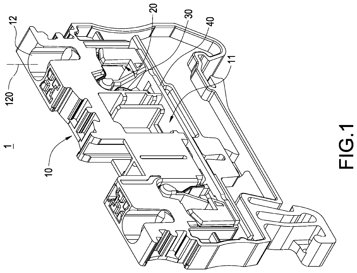
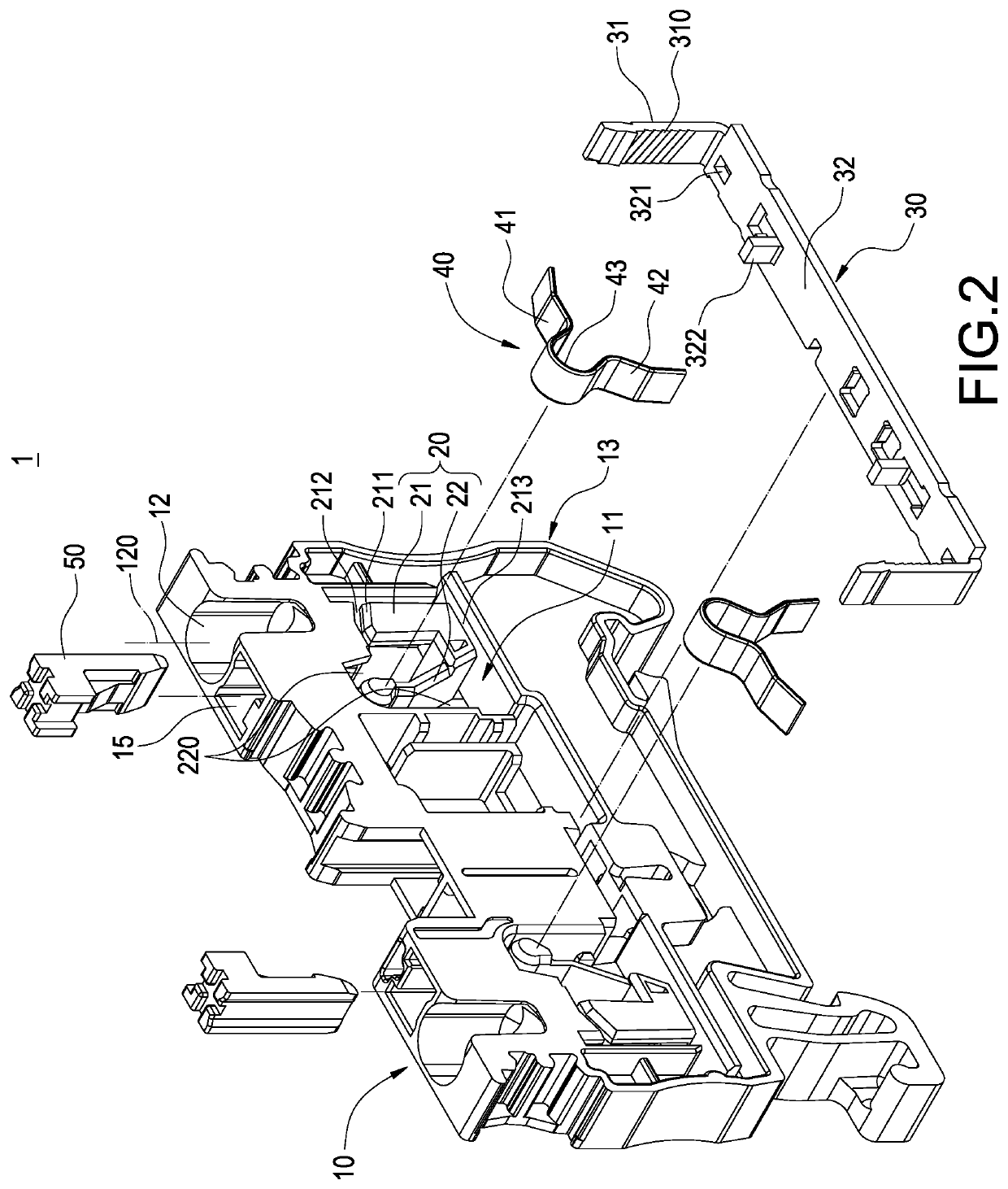
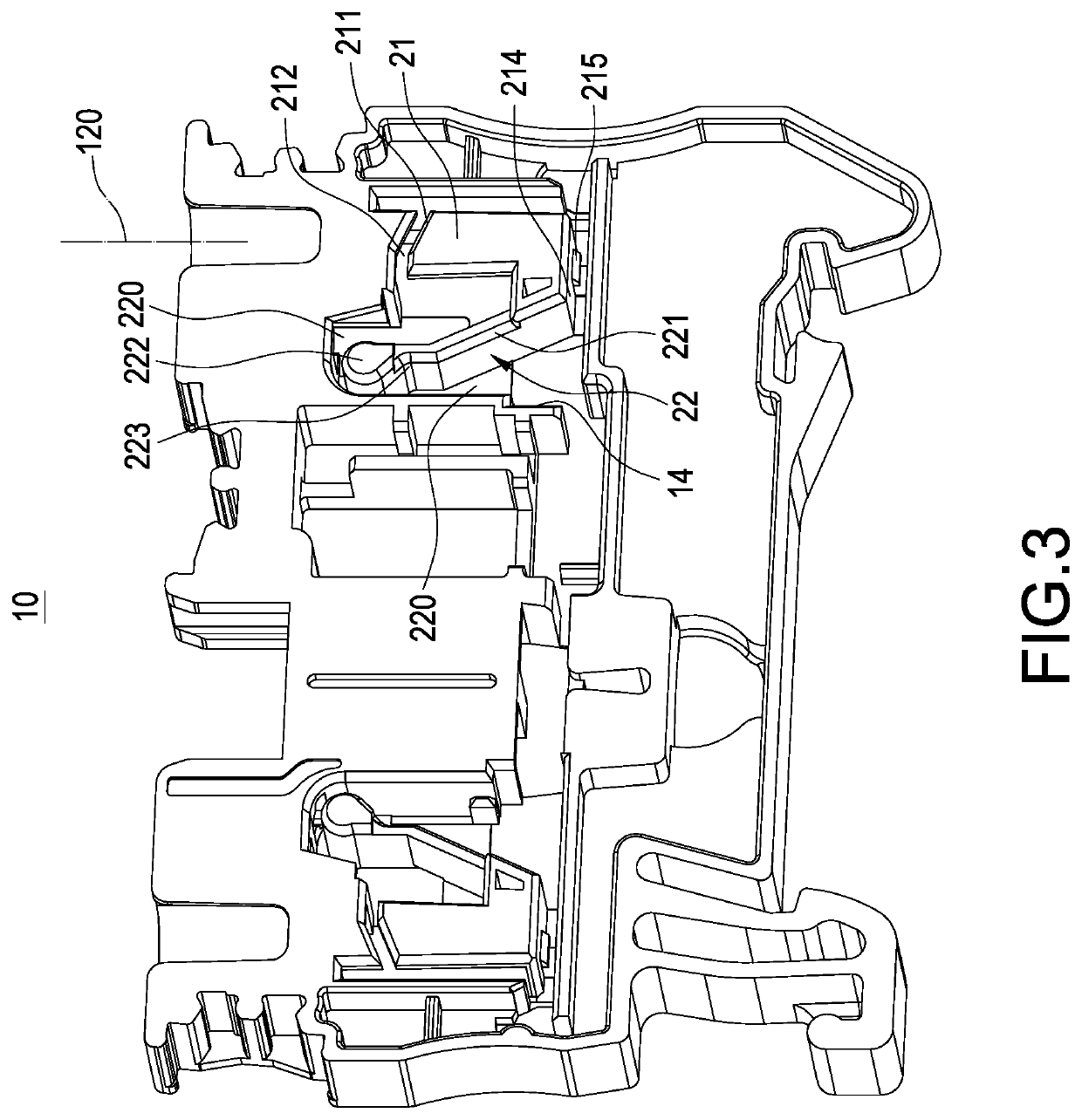
[0014]Please refer to FIGS. 1-3, which are a perspective view, an exploded view and a perspective view of the insulative base of the terminal block of the disclosure. The disclosure provides a terminal block 1 including an insulative base 10, a guiding structure 20, a conducting terminal 30 and an elastic strip 40. The guiding structure 20 is disposed in the insulative base 10 and is formed with the insulative base 10 in one piece. The conducting terminal 30 and the elastic strip 40 are assembled in the insulative base 10 to form the terminal block 1. The details of the terminal block 1 are described below.

[0015]The insulative base 10 has an accommodating space 11 and an insertion hol...


PUM


Abstract

This disclosure is a terminal block. An insulative base includes an accommodating space and an insertion hole. The insulative base includes a lateral opening. A guiding structure is disposed in the accommodating space and includes a guiding plate and a guiding arm. A passing space is formed between the insulative base and the guiding plate. An L-shaped space is formed between the guiding plate and the insulative base. A U-shaped space is formed between the guiding arm and the insulative base. A conducting terminal is positioned in the L-shaped space. An elastic strip includes an abutting section, a positioning section and a U-shaped section connected therebetween. The elastic strip is inserted to the passing space and the U-shaped space to be connected with the guiding arm.

Description

BACKGROUNDTechnical Field[0001]The disclosure relates a terminal block, particularly to a terminal block with an elastic strip.Description of Related Art[0002]A terminal block is an electric connection device composed of an insulative base and a guiding structure for electrically connecting multiple wires or using as the data transmission line. A terminal block includes a conducting terminal and an elastic strip. The assembly method places the conducting terminal in the insertion base first, and then bends and positions the elastic strip in the conducting terminal. As a result, when a wire is inserted into the insertion base, the wire can be clamped between the elastic strip and the conducting terminal by the elasticity of the elastic strip.[0003]However, in the manufacturing process of the related-art terminal blocks, the elastic strip of the guiding structure needs to be bent with a large angle to be placed in the insulative base. And the elastic strip is also bent with a large an...

Claims


Application Information

Patent Timeline
Patent Type & Authority Patents(United States)
IPC IPC(8): H01R9/24H01R13/24H01R13/502
CPCH01R9/2416H01R13/24H01R13/502H01R9/26H01R4/48365
Inventor WU, SHANG-TSAI
Owner DINKLE ENTERPRISE CO LTD
Why Eureka
Try Eureka