

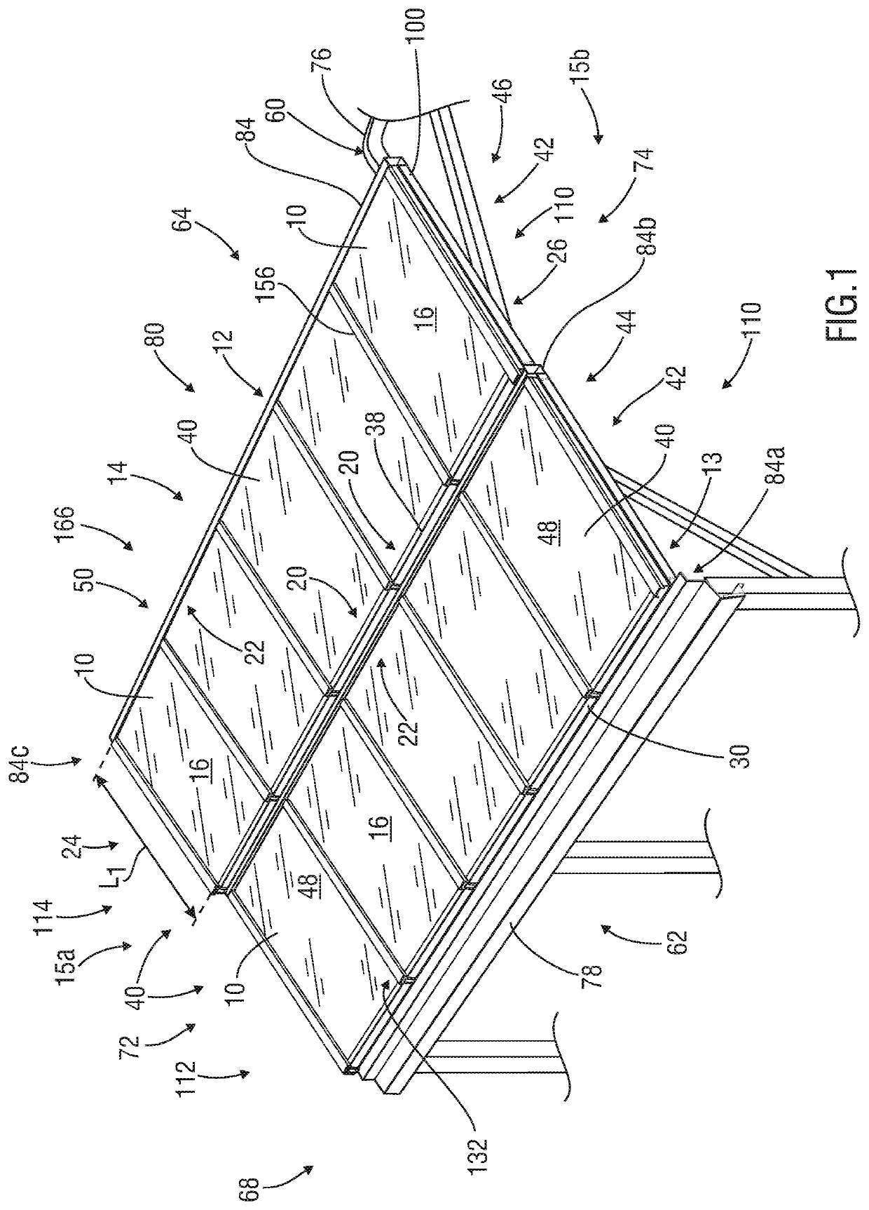
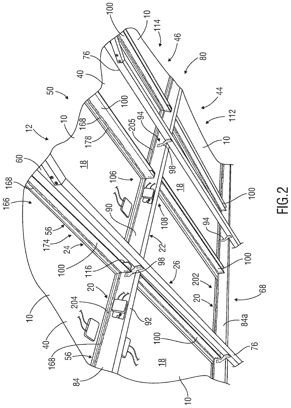
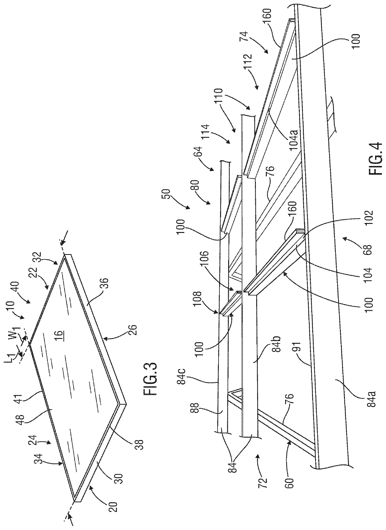
Systems, apparatus and methods for mounting panels upon, or to form, a pitched roof, wall or other structure
a technology of systems and apparatus, applied in the field of systems and apparatus for mounting panels on, can solve the problems of sacrificing some of the critical functionality of the panels, existing techniques are believed to have one or more limitations,
- Summary
- Abstract
- Description
- Claims
- Application Information
AI Technical Summary
Benefits of technology
Problems solved by technology
Method used
Image

Examples
Embodiment Construction
[0031]Characteristics and advantages of the present disclosure and additional features and benefits will be readily apparent to those skilled in the art upon consideration of the following detailed description of exemplary embodiments and / or referring to the accompanying figures. It should be understood that the description herein and appended drawings, being of example embodiments, are not intended to limit the claims of this patent (or any patent or patent application claiming priority hereto). On the contrary, the intention is to cover all modifications, equivalents and alternatives falling within the spirit and scope of this disclosure and the relevant claims. Many changes may be made to the particular embodiments and details disclosed herein without departing from such spirit and scope.
[0032]In showing and describing preferred embodiments in the appended figures, common or similar elements are referenced with like or identical reference numerals or are apparent from the figures...
PUM
 Abstract
Description
Claims
Application Information