Transmission actuator attachment structure of vehicle automatic driving device

a technology of automatic driving device and transmission actuator, which is applied in the direction of vehicle testing, structural/machine measurement, instruments, etc., can solve the problem of vibration and other problems

Active Publication Date: 2022-09-20
MEIDENSHA ELECTRIC MFG CO LTD
View PDF63 Cites 1 Cited by
  • Summary
  • Abstract
  • Description
  • Claims
  • Application Information

AI Technical Summary

Benefits of technology

[0014]In this manner, the transmission actuator can be mounted on the actuator support plate with the transmission actuator being reversed 180 degrees. The automatic vehicle driving device can therefore meet both of the so-called right-hand drive vehicle and the so-called left-hand drive vehicle. Since the actuator support plate is supported in the horizontal attitude and the base plate of the transmission actuator is stacked or mounted on this actuator support plate, rigidity of support of the transmission actuator unit (131) and the actuator support plate (105) can be high.
[0034]According to the present invention, the transmission actuator can be mounted with the transmission actuator easily reversed (or turned) 180 degrees. It is therefore possible to meet both of the so-called right-hand drive vehicle and the so-called left-hand drive vehicle by one automatic vehicle driving device. Further, since the transmission actuator is supported by the actuator support plate with the base plate of the transmission actuator mounted on the actuator support plate settled in the horizontal attitude in the both mounting attitudes, rigidity of support of the transmission actuator and the actuator support plate is high, and vibrations of the transmission actuator do not easily occur.

Problems solved by technology

Regarding the automatic vehicle driving device of Patent Document 1, it is not possible to meet both of the right-hand drive vehicle and the left-hand drive vehicle, and thus there is a need to separately prepare an automatic vehicle driving device for the right-hand drive vehicle and an automatic vehicle driving device for the left-hand drive vehicle.
However, since the heavy transmission actuator is supported as a whole by the cylindrical columnar member by the so-called cantilever structure, rigidity of the support of the cylindrical columnar member is lowered, and consequently, for instance, vibrations tend to occur at a hand portion located at a top end of the transmission actuator.

Method used


Image

  • Transmission actuator attachment structure of vehicle automatic driving device
  • Transmission actuator attachment structure of vehicle automatic driving device
  • Transmission actuator attachment structure of vehicle automatic driving device

Examples


second embodiment

[0290]Next, an automatic vehicle driving device 301 of a second embodiment will be described.

[0291][General Configuration of Automatic Vehicle Driving Device 301 of Second Embodiment]

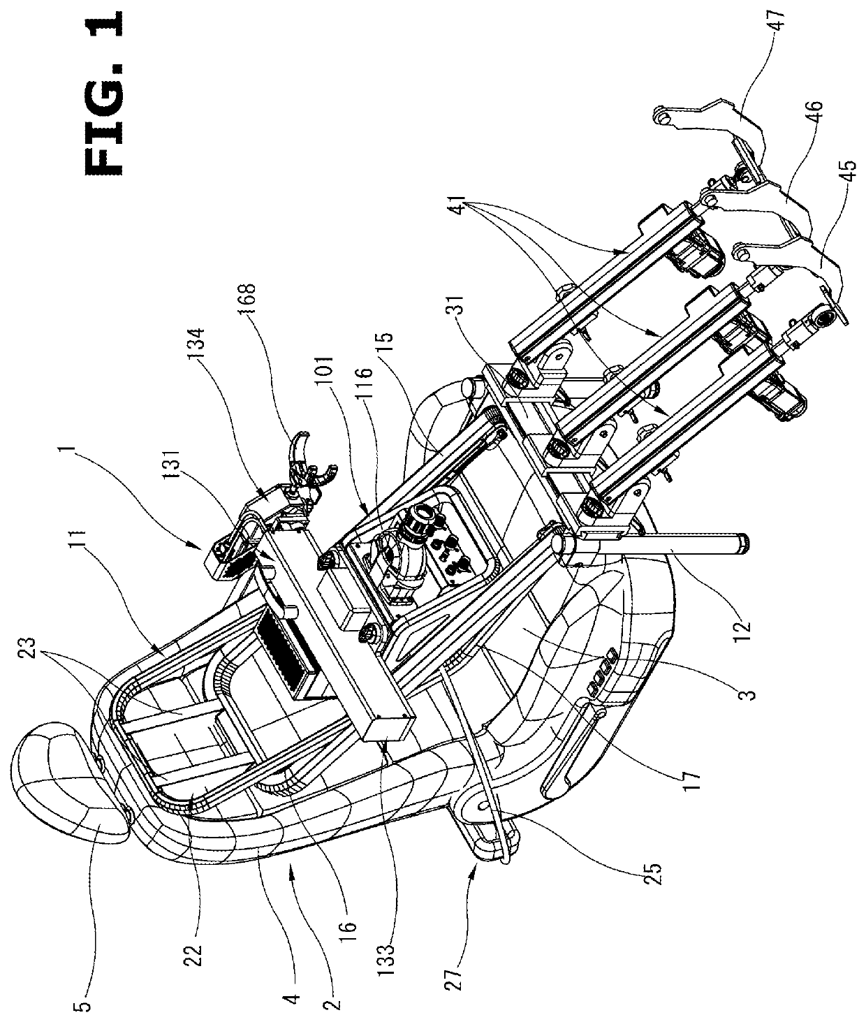
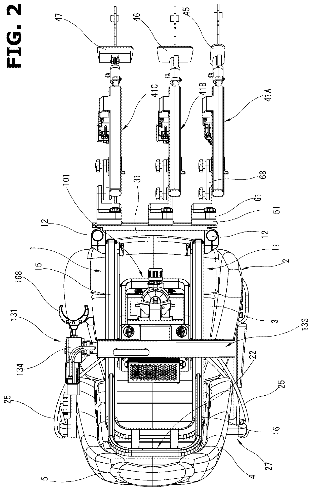
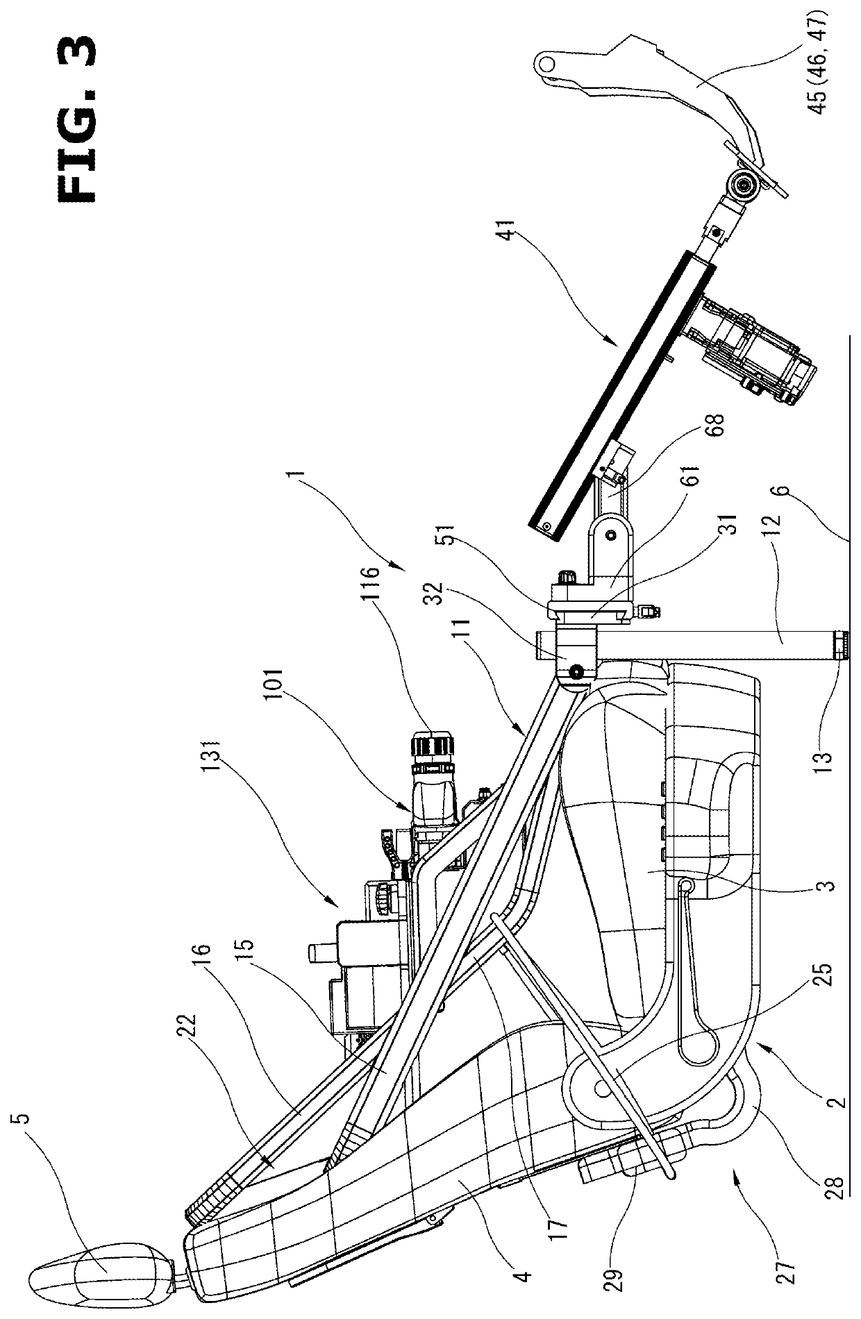
[0292]FIGS. 43 to 46 show a state in which the automatic vehicle driving device 301 of the second embodiment is mounted above a driver's seat 302 of a vehicle. FIGS. 47 to 51 show the automatic vehicle driving device 301 in its entirety with the device 301 dismounted from the vehicle. This automatic vehicle driving device 301 is used when carrying out a running test of the vehicle on a chassis dynamometer (not shown). The automatic vehicle driving device 301 performs a pedal operation of an accelerator pedal etc. and a shift-lever operation of a transmission by signals from an external controller placed outside the vehicle.

[0293]Here, as described later, the automatic vehicle driving device 301 of the present embodiment can be used for a vehicle with a manual transmission having a clutch pedal and for a...


PUM


Abstract

A transmission actuator unit (131) is fixed on a actuator support plate (105) of a connection box unit (101) through a pair of lock mechanisms (143). A pair of grommets (121), with which lock pins (144) are engaged, are provided at both of a front side and a rear side of the actuator support plate (105). Then, the transmission actuator unit (131) can be selectively mounted on the actuator support plate (105) in either of two attitudes that are reversed 180 degrees according to vehicle types. Since a base plate of the transmission actuator unit (131) is mounted on the actuator support plate (105) settled in a horizontal attitude, rigidity of support of the transmission actuator unit (131) and the actuator support plate (105) is high.

Description

TECHNICAL FIELD[0001]The present invention relates to an automatic vehicle driving device that performs a shift-lever operation of a transmission etc., for instance, when carrying out a running test of a vehicle on a chassis dynamometer, and more particularly to amounting structure of a transmission actuator of the automatic vehicle driving device.BACKGROUND ART[0002]When carrying out a running test of a vehicle on a chassis dynamometer, an automatic vehicle driving device that performs a pedal operation and a shift-lever operation of the vehicle in place of a driver is generally used. To perform the shift-lever operation, the automatic vehicle driving device has a transmission actuator.[0003]Patent Documents 1 and 2 each disclose, as a transmission actuator, a configuration in which a lateral-direction actuator that actuates a shift lever along a vehicle width direction and a longitudinal-direction actuator that actuates the shift lever along a vehicle longitudinal direction are co...

Claims


Application Information

Patent Timeline
Patent Type & Authority Patents(United States)
IPC IPC(8): G01M17/007
CPCG01M17/0074G01M17/06
Inventor KODAMA, AKIHIKOOKAZAKI, NOBUO
Owner MEIDENSHA ELECTRIC MFG CO LTD
Why Eureka
Try Eureka