
Expandable and adjustable lordosis interbody fusion system

a lordosis and fusion system technology, applied in the field of lumbar back pain surgery procedures and equipment, can solve the problems of significant invasive activity of patients, limited function of present lateral interbody fusion cage devices, etc., and achieve the effect of facilitating the insertion of bone graft material

Active Publication Date: 2022-09-27
ADCURA INC
View PDF58 Cites 1 Cited by
  • Summary
  • Abstract
  • Description
  • Claims
  • Application Information

AI Technical Summary

Benefits of technology

The present invention is a device for in situ adjustment during spine surgery. It allows for both expansion of the fusion cage and adjustment of the lordotic angle, which helps adjust the spkin alignment. Additionally, it allows for the introduction of bone graft material at the operation site while the device is in place. This allows for geometric variability to accommodate the unique needs of each patient. The device includes a track for stability, drive shafts for manipulation, and a locking mechanism. The technical effects of this invention include improved outcomes and minimized damage to the spine during surgery.

Problems solved by technology

It is unlikely that these values can be determined precisely prior to the operation, which is a drawback in present procedures.
Present lateral interbody fusion cage devices are generally limited to providing height expansion functions, but not a lordotic adjustment capability.
In implementing a trial-and-error approach to sizing and fitting the interbody fusion cage into the target region for the particular geometric configuration for that patient, the patient is subjected to significant invasive activity.

Method used


Image

  • Expandable and adjustable lordosis interbody fusion system
  • Expandable and adjustable lordosis interbody fusion system
  • Expandable and adjustable lordosis interbody fusion system

Examples


Embodiment Construction

.

BRIEF DESCRIPTION OF THE DRAWINGS FIGURES

[0017]An embodiment of the present invention is described herein with reference to the following drawing figures, with greater emphasis being placed on clarity rather than scale:

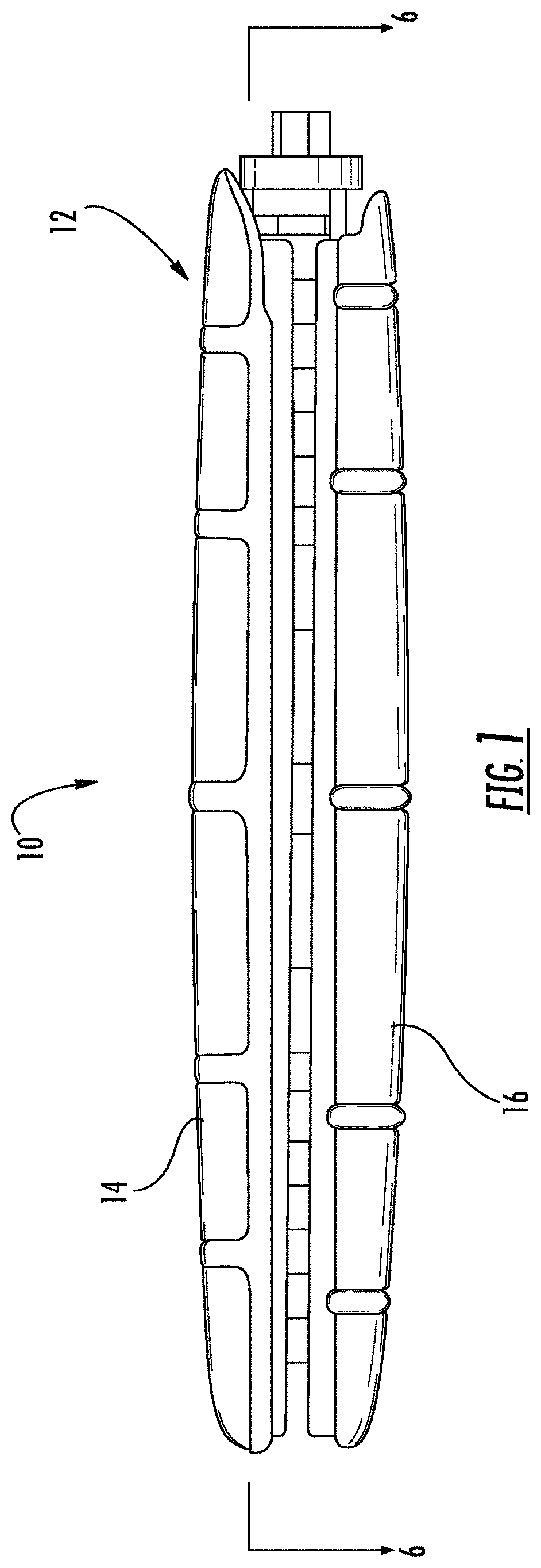
[0018]FIG. 1 is a view in side elevation from the side of the expandable shell device.

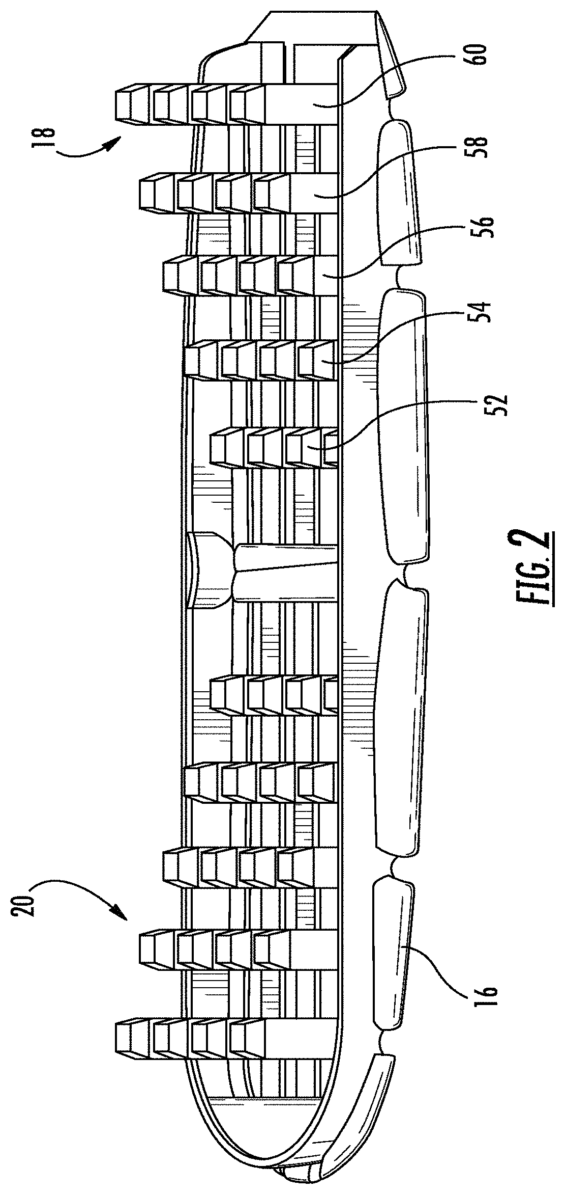
[0019]FIG. 2 is a perspective view of a bottom section of the expandable shell.

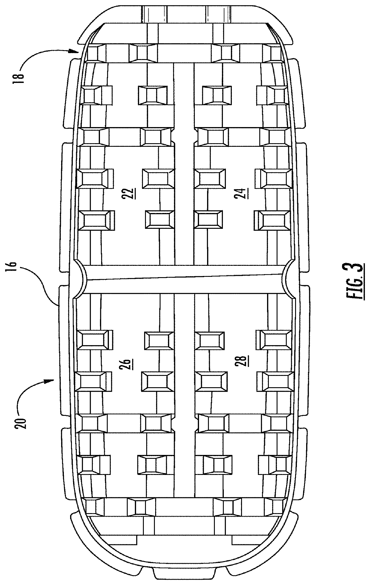
[0020]FIG. 3 is a top plan view of the bottom section of the expandable shell.

[0021]FIG. 4 is a top plan view of the expandable shell device.

[0022]FIG. 5 is a perspective view of a tapered external helical threaded member.

[0023]FIG. 5A is a view in side elevation from the side of the tapered external helical threaded member.

[0024]FIG. 5B is a view in side elevation from the front of the tapered external helical threaded member.

[0025]FIG. 6 is a cross-sectional view of the device taken along lines 6-6 in FIG. 1.

[0026]FIGS. 7A-7C are a series of views in side elevation of the device as it undergoes expansio...


PUM


Abstract

A spinal implant device for placement between vertebral bodies includes a housing, at least one screw member in the housing, and at least one drive shaft operably engageable with the screw member. The housing includes a first shell member and a second shell member. At least the first shell member has step tracking comprising a plurality of individual riser members for receiving the at least one screw member. The height of the plurality of individual riser members may change along the step tracking. The drive shaft may be operable to rotate the at least one screw member, causing the at least one screw member to move on the plurality of individual riser members. The at least one screw member comprises an external helical thread having a thickness configured to fit in the gaps between adjacent individual riser members, and is engageable with the first and second shell members, whereby the first and second shell members move relative to each other in response to the rotation of the at least one screw member to effect an expansion of the housing or a contraction of the housing from the expansion by reversing the rotation of the at least one screw member.

Description

RELATED APPLICATIONS[0001]This application is a continuation-in-part of U.S. application Ser. No. 16 / 001,852 filed Jun. 6, 2018 entitled “EXPANDABLE AND ADJUSTABLE LORDOSIS INTERBODY FUSION SYSTEM,” which is a continuation of U.S. application Ser. No. 15 / 859,241 filed Dec. 29, 2017 entitled “EXPANDABLE AND ADJUSTABLE LORDOSIS INTERBODY FUSION SYSTEM,” issued as U.S. Pat. No. 10,188,527 on Jan. 29, 2019, which is a continuation of Ser. No. 14 / 473,200 filed Aug. 29, 2014 entitled “EXPANDABLE AND ADJUSTABLE LORDOSIS INTERBODY FUSION SYSTEM,” issued as U.S. Pat. No. 9,889,019 on Feb. 13, 2018, which claims priority to U.S. provisional patent application No. 61 / 871,780 filed Aug. 29, 2013 entitled “EXPANDABLE LATERAL INTERBODY FUSION SYSTEM,” the disclosures of all of which are hereby incorporated by reference in their entirety.[0002]This application claims priority to U.S. provisional patent application No. 62 / 736,649 filed Sep. 26, 2018 entitled “EXPANDABLE AND ADJUSTABLE LORDOSIS INTE...

Claims


Application Information

Patent Timeline
Patent Type & Authority Patents(United States)
IPC IPC(8): A61F2/44A61F2/46A61F2/30
CPCA61F2/447A61F2/4455A61F2/4611A61F2/4465A61F2002/30462A61F2002/30507A61F2002/30523A61F2002/30525A61F2002/30538A61F2002/30556A61F2002/30566A61F2002/4627A61F2002/30537
Inventor ROGERS, ANDREWBURROWS-OWNBEY, ROBYN
Owner ADCURA INC
Learn More