
Refill friction stir spot welding tool and end effector

a technology of friction stir and welding tool, which is applied in welding apparatus, metal-working equipment, manufacturing tools, etc., can solve the problems of periodic replacement, undesirable down time, and plastic workpiece material displacement within the sleev

Active Publication Date: 2022-10-04
LINCOLN GLOBAL INC
View PDF23 Cites 0 Cited by
  • Summary
  • Abstract
  • Description
  • Claims
  • Application Information

AI Technical Summary

Benefits of technology

The present invention provides a quick connect robotic refill friction stir spot welding tool that allows for easy attachment and detachment of the tool to the refill friction stir spot welding end effector. This results in quick and easy replacement of the tool without having to stop the welding process, which saves time and increases efficiency. The tool includes a clamp with mounting tabs, a friction sleeve with mounting tabs, and a friction pin with a mounting head that all engage with the spindle of the refill friction stir spot welding end effector. The clamp can be rotated less than 180 degrees, while the friction sleeve and friction pin can be rotated less than 180 degrees to securely attach and detach the tool.

Problems solved by technology

The sleeve is pushed into the workpiece while the pin is retracted away from the workpiece, which causes a displacement of the plastic workpiece material within the sleeve.
Over time, refill friction stir spot welding tools can become clogged, worn, etc. so that they require periodic replacement.
Replacing refill friction stir spot welding tools is typically labor-intensive and time-consuming, and, thus, can be expensive and lead to undesirable down time.

Method used


Image

  • Refill friction stir spot welding tool and end effector
  • Refill friction stir spot welding tool and end effector
  • Refill friction stir spot welding tool and end effector

Examples


Embodiment Construction

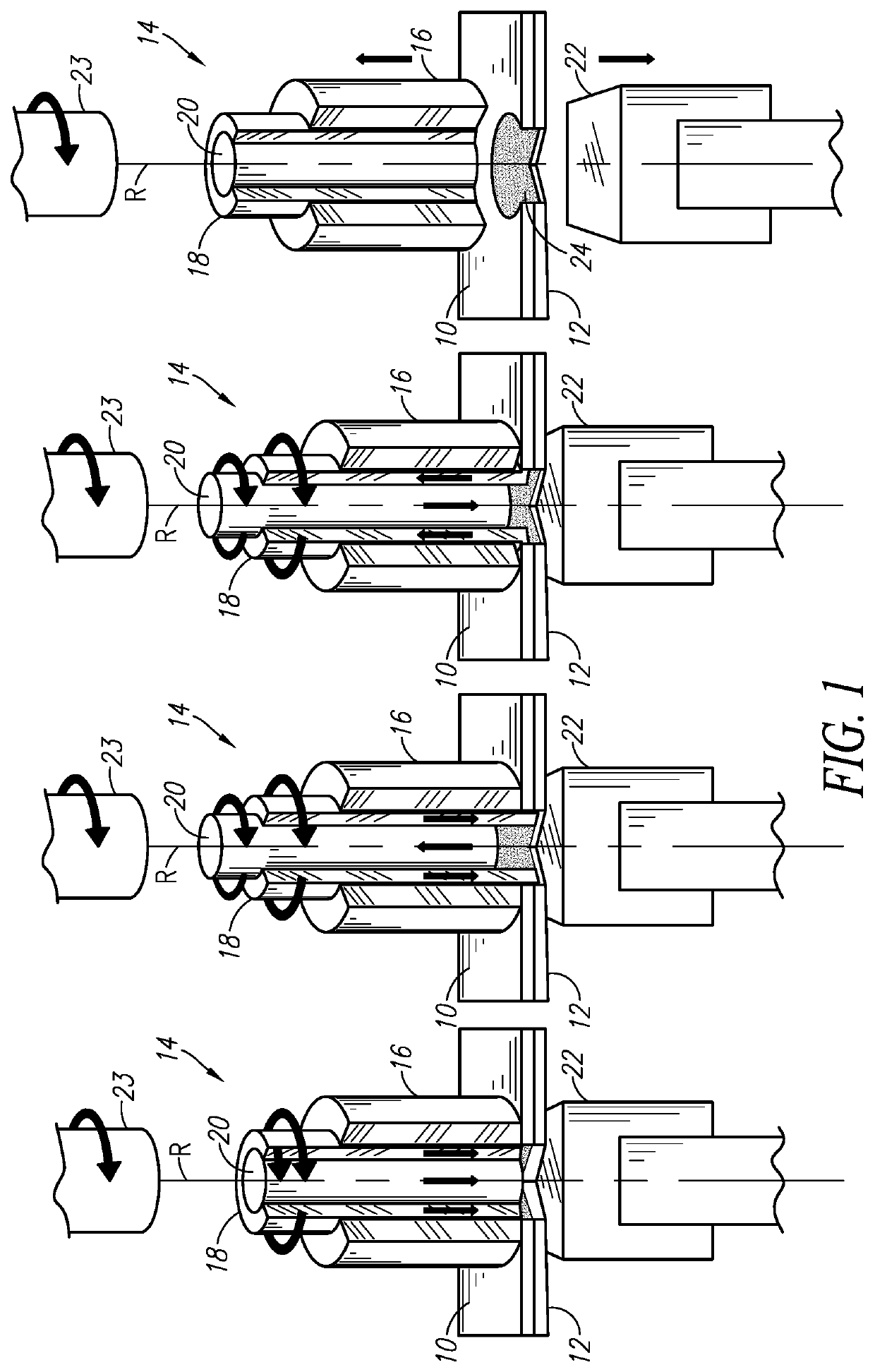
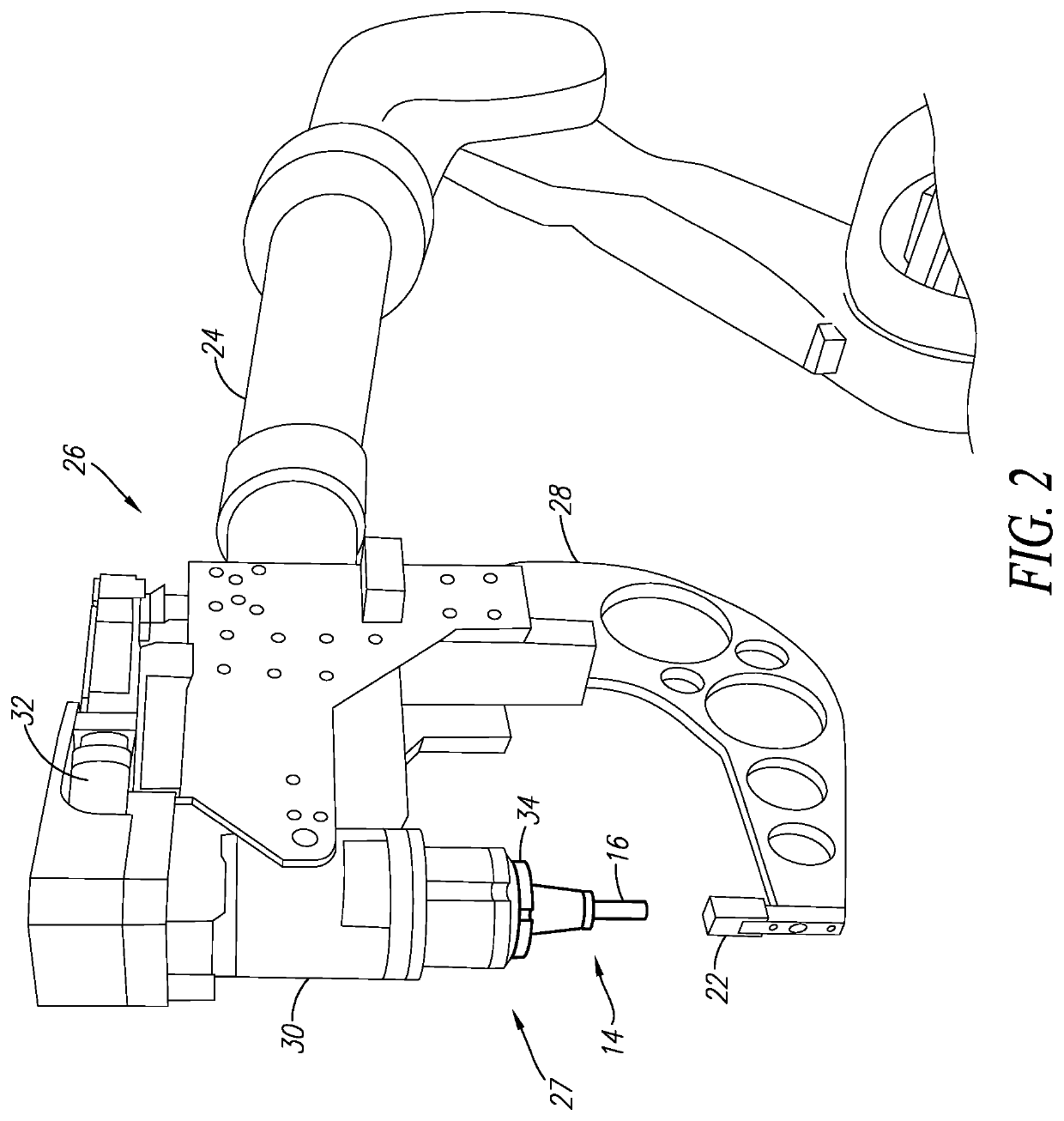
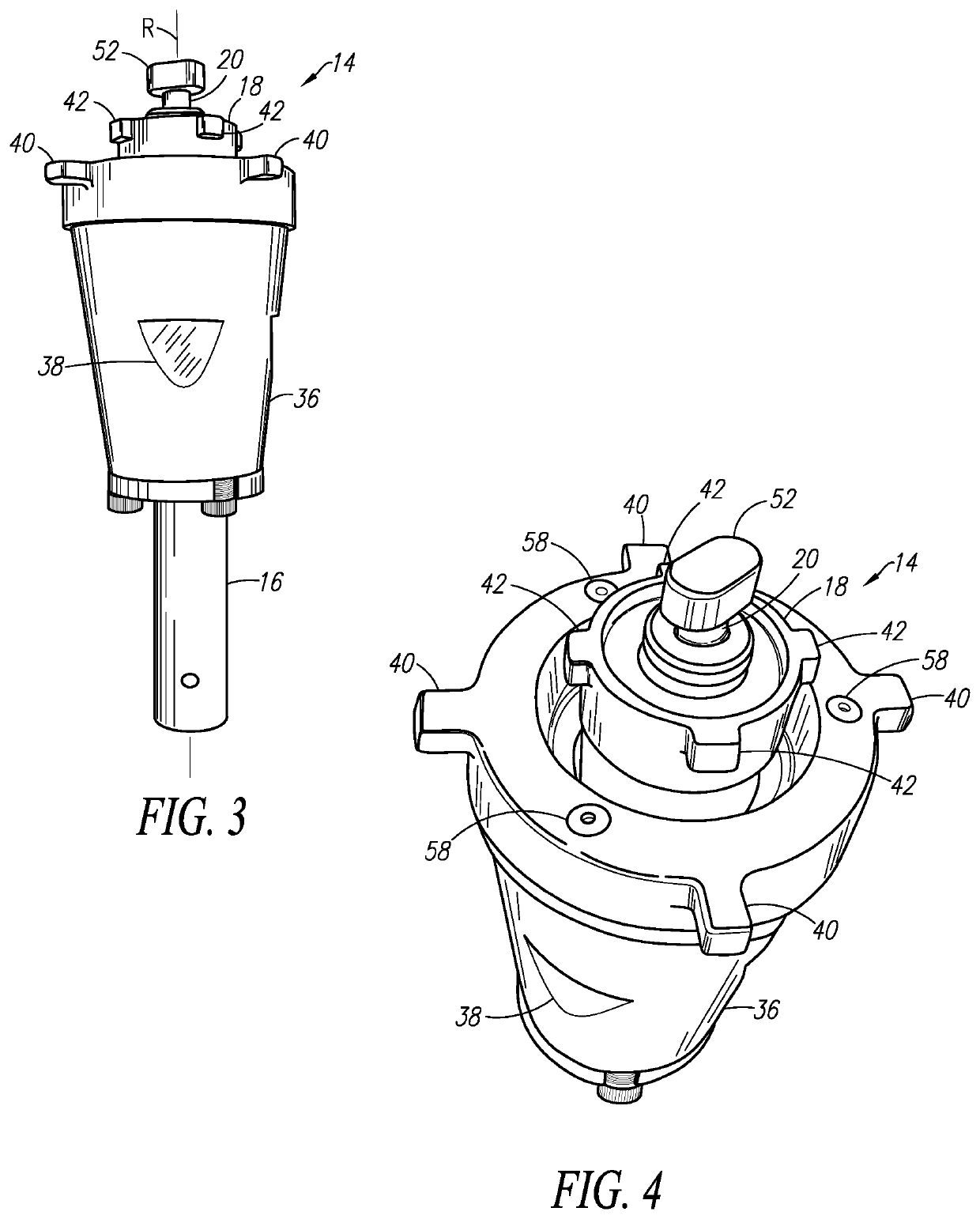
[0020]The present invention relates to refill friction stir spot welding devices, such as robotic refill friction stir spot welding tools and end effectors. The present invention will now be described with reference to the drawings, wherein like reference numerals are used to refer to like elements throughout. It is to be appreciated that the various drawings are not necessarily drawn to scale from one figure to another nor inside a given figure, and in particular that the size of the components are arbitrarily drawn for facilitating the understanding of the drawings. In the following description, for purposes of explanation, numerous specific details are set forth in order to provide a thorough understanding of the present invention. It may be evident, however, that the present invention can be practiced without these specific details. Additionally, other embodiments of the invention are possible and the invention is capable of being practiced and carried out in ways other than as ...


PUM

PropertyMeasurementUnit
pressureaaaaaaaaaa
displacementaaaaaaaaaa
forceaaaaaaaaaa

Abstract

A quick connect refill friction stir spot welding tool includes a clamp having a first radially-projecting mounting tab configured for engaging a first mounting slot in a refill friction stir spot welding weld head. A friction sleeve is located coaxially within the clamp and has a second radially-projecting mounting tab configured for engaging a second mounting slot in the refill friction stir spot welding weld head. The second radially-projecting mounting tab is located higher along an axis of the tool than the first radially-projecting mounting tab, and radially inward thereof. A friction pin is located coaxially within the clamp and friction sleeve. The clamp and friction sleeve are attachable to and detachable from the refill friction stir spot welding weld head by rotations through less than 360 degrees.

Description

BACKGROUND OF THE INVENTIONField of the Invention[0001]The present invention relates to refill friction stir spot welding devices, and in particular to robotic refill friction stir spot welding tools and end effectors.Description of Related Art[0002]Refill friction stir spot welding is a solid state joining process. It can be used to weld two or more overlapping metal workpieces. In refill friction stir spot welding, a sleeve and a pin within the sleeve are pressed against one of the workpieces and rotated to heat the workpieces. The workpiece material achieves a plastic state from heat and pressure. The sleeve is pushed into the workpiece while the pin is retracted away from the workpiece, which causes a displacement of the plastic workpiece material within the sleeve. The sleeve and pin are then returned to their initial flush condition to force the displaced material back toward the workpieces, thereby forming a generally flush spot weld. Refill friction stir spot welding devices...

Claims


Application Information

Patent Timeline
Patent Type & Authority Patents(United States)
IPC IPC(8): B23K20/00B23K20/12
CPCB23K20/1255B23K20/1265B23K20/127B23K20/12B23K20/1245B23K20/26
Inventor WENNING, NATHAN P.WILL, JOHN A.SCHWIETERMAN, JAMES R.EBBING, AUSTIN J.
Owner LINCOLN GLOBAL INC
Learn More