Vehicle surrounding display apparatus

a technology for display apparatuses and vehicles, applied in television systems, instruments, transportation and packaging, etc., can solve problems such as difficulty in driving, insufficient display of another image, and small size of the second display area

Active Publication Date: 2022-10-04
TOYOTA JIDOSHA KK +1
View PDF15 Cites 0 Cited by
  • Summary
  • Abstract
  • Description
  • Claims
  • Application Information

AI Technical Summary

Benefits of technology

[0019]In the present invention apparatus, when the first mode is selected as the display mode, the display control means generates the first bird's-eye view image of the vehicle and the first surrounding region thereof seen from the bird's-eye view and displays this generated image in the first display area on the display screen. Besides, when the second mode is selected as the display mode, the display control means generates the second bird's-eye view image of the vehicle and the second surrounding region thereof wider than the first surrounding region seen from the bird's-eye view and displays this generated image in the first display area which is the same area as the area where the first bird's-eye view image is displayed. The size of this first display area is fixed. According to this configuration, the size of the first display area is prevented from being changed due to a change in the display range of the surrounding region in the bird's-eye view image, and therefore it is prevented that the size of the second display area (an area where the first another image different from the first bird's-eye view image or the second another image different from the second bird's-eye view image is displayed) on the display screen is changed. Therefore, the present invention apparatus can properly change the display range of the surrounding region in the bird's-eye view image between two different display modes while suitably displaying another image.
[0025]According to this configuration, the display range of the surrounding region (the second surrounding region) in the bird's-eye view image (the second bird's-eye view image) of when the parking assist control is being performed becomes wider than the display range of the surrounding region (the first surrounding region) in the bird's-eye view image (the first bird's-eye view image) of when the parking assist control is not being performed. Therefore, when the parking assist control is performed, the target parking position is easily displayed in the bird's-eye view image. This enables the driver to confirm (check) the target parking position and / or whether or not there is an obstacle on the target path by referring to the bird's-eye view image. According to this configuration, the surrounding region in the bird's-eye view image can be displayed in a suitable display range for the parking assist control.
[0029]In the traveling direction image, a traveling direction front region and a traveling direction left and right region are displayed, where the traveling direction front region is a region positioned ahead of the traveling direction of the vehicle and the traveling direction left and right region is a region positioned at a left part and a right part of the traveling direction front region. According to this configuration, the angle of view of the traveling direction image (the second another image) of when the parking assist control is being performed is narrowed compared with the angle of view of the traveling direction image (the first another image) of when the parking assist control is not being performed. That is, when the parking assist control is performed, the display range of the traveling direction left and right region in the traveling direction image is narrowed compared with when the parking assist control is not performed. The size of the second display area (a display area where the traveling direction image is displayed) remains unchanged (is fixed) between two different modes. Therefore, if the display range of the traveling direction left and right region in the traveling direction image is narrowed, the traveling direction front region is displayed in a magnified manner by that amount. Hence, when the parking assist control is performed, the driver can more easily confirm a process through which the vehicle travels by referring to the traveling direction image.
[0030]Besides, in general, in a case of a relatively wide angle of view, a left and right range in an image is displayed in a relatively distorted manner, whereas in a case of a relatively narrow angle of view, the left and right range in the image is displayed with little distortion. Therefore, according to the configuration above, when the parking assist control is performed, the traveling direction front region in the traveling direction image is displayed with little distortion. Hence, the traveling direction front region in the traveling direction image can be displayed in a suitable display manner for the parking assist control.
[0035]In this configuration, when the parking assist control is being performed, not only the target stop position but also the target parking position are displayed in the bird's-eye view image at least until the vehicle reaches the target stop position along the first path. Therefore, when the vehicle travels forward (advances) along the first path, the driver can confirm not only the first path but also the second path by referring to the bird's-eye view image. This enables the driver to check whether or not there is an obstacle not only on the first path but also on the second path, and therefore when some obstacle is detected on the target path, the parking assist control can be immediately stopped by a driving operation by the driver. According to this configuration, the surrounding region in the bird's-eye view image can be displayed in a suitable display range for the parking assist control. It should be noted that “to display both of the target stop position and the target parking position in the bird's-eye view image” means to display at least a part of the target stop position and at least a part of the target parking position in the bird's-eye view image.

Problems solved by technology

However, the prior art apparatus increases the size of the first display area itself when displaying the surrounding region in the bird's-eye view image in the wide display range, and therefore a size of the second display area may become smaller in some positional relationships (layouts) between the first display area and the second display area.
In this case, it is likely that another image displayed on the second display area becomes small and thus another image is not displayed properly (that is, another image becomes difficult to see for the driver).

Method used


Image

  • Vehicle surrounding display apparatus
  • Vehicle surrounding display apparatus
  • Vehicle surrounding display apparatus

Examples


modification example 1

[0122]Next, a description about a vehicle surrounding display apparatus according to a modification example 1 of the embodiment of the present invention (hereinafter, also referred to as a “first modification apparatus”) will be made, referring to FIG. 10. The present modification example differs from the above embodiment in that in the above embodiment, the PVM mode and the IPA mode are both switched from the navigation mode, whereas in the present modification example, the PVM mode and the IPA mode can be switched to each other without an intervention of the navigation mode.

[0123]When the ignition switch is turned on, the DSECU 10 performs a routine shown by a flowchart in FIG. 10. When the DSECU starts processing from a step S1000 after the ignition switch is turned on, the DSECU 10 sets, at a step S1002, a display mode to the PVM mode. Thereby, among a plurality of display patterns which the PVM mode includes, a display pattern corresponding to the shift position and the number ...

modification example 2

[0128]Next, a description about a vehicle surrounding display apparatus according to a modification example 2 of the embodiment of the present invention (hereinafter, also referred to as a “second modification apparatus”) will be made, referring to FIG. 11 and FIG. 12. In the description below, the same reference numeral will be assigned to members having the same configuration as the members of the vehicle surrounding display apparatus according to the embodiment, and a detailed description for them will be omitted.

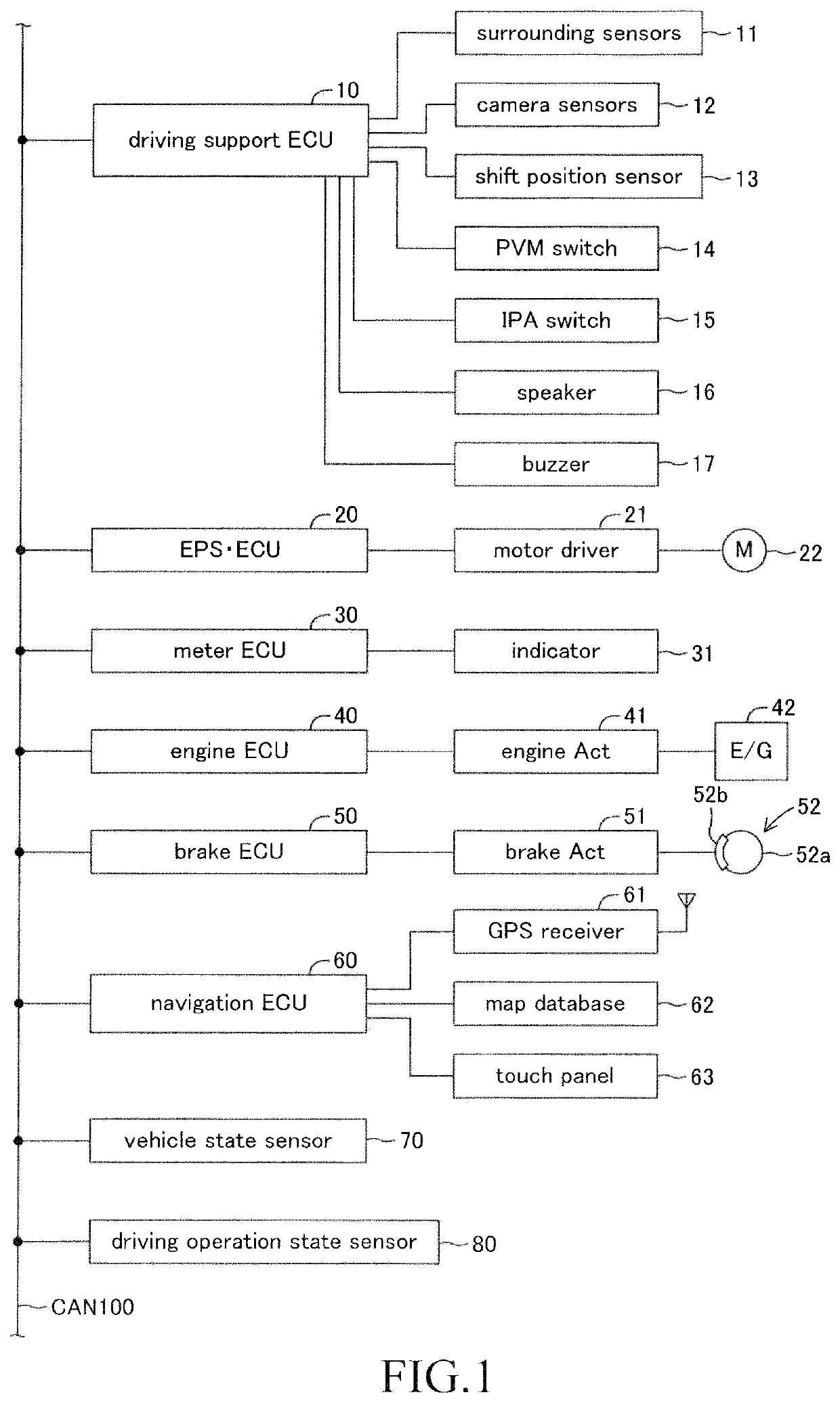
[0129]As shown in FIG. 11, the second modification apparatus has an IPA-R coordinated switch 18 connected to the DSECU 10, which is a difference from the present embodiment apparatus. The IPA-R coordinated switch 18 is arranged in the vicinity of the PVM switch 14 and the IPA switch 15. When the IPA-R coordinated switch 18 is pressed, the IPA-R coordinated function is activated. When the driver stops the own vehicle in front of the target parking position and moves the s...


PUM


Abstract

A vehicle surrounding display apparatus comprises a display control means for displaying images, each of which corresponding to each of a plurality of display modes on a display screen. The display control means, when at a first mode, generates a first bird's-eye view image of a vehicle and a first surrounding region thereof seen from a bird's-eye view to display this image in a first display area with a fixed size on the display screen and generates a first another image to display this image in a second display area with a fixed size on the display screen, and when at a second mode, generates a second bird's-eye view image of a vehicle and a second surrounding region thereof wider than the first surrounding region to display this image in the first display area and generates a second another image to display this image in the second display area.

Description

CROSS-REFERENCE TO RELATED APPLICATION[0001]The present application claims priority to Japanese Patent Application No. 2017-130288 filed on Jul. 3, 2017, which is incorporated herein by reference in its entirety.TECHNICAL FIELD[0002]The present invention relates to a vehicle surrounding display apparatus for displaying on a display screen an image (a bird's-eye view image) of a vehicle and a surrounding region thereof seen from a bird's-eye view and another image different from the bird's-eye view image.BACKGROUND ART[0003]A vehicle surrounding display apparatus has been conventionally known. This apparatus is mounted in a vehicle and displays on a display screen with a predetermined size a bird's-eye view image and another image different from the bird's-eye view image, the bird's-eye view image being an image of the vehicle and a surrounding region thereof seen from a bird's-eye view (for example, refer to Japanese Patent Application Laid-Open (kokai) No. 2015-76645).[0004]A vehic...

Claims


Application Information

Patent Timeline
Patent Type & Authority Patents(United States)
IPC IPC(8): B60W30/06H04N5/262B60W50/14G06F3/147B60R1/00B60K35/00B62D15/02
CPCB60W30/06B60K35/00B60R1/00B60W50/14B62D15/027B62D15/0285G06F3/147H04N5/2624H04N5/2628B60K2370/152B60K2370/171B60K2370/176B60K2370/21B60K2370/52B60R2300/607B60W2050/146B60W2420/42H04N7/18
Inventor YORIFUJI, YAMATOMAEJIMA, KOHEIITOH, TAKUYAYAMAZAKI, ERIKOKIYO, KOUEIHATAKEYAMA, YUKIKO
Owner TOYOTA JIDOSHA KK
Why Eureka
Try Eureka