Method and device for remote monitoring and diagnosis of field equipment

a field equipment and remote monitoring technology, applied in the field of condition monitoring of field equipment, can solve the problems of excess network access, failure to leverage the high data rate available, and the cost of operation per field device, so as to limit the time the communication channel is blocked, and affect the responsiveness of applications

Pending Publication Date: 2021-09-23
ABB (SCHWEIZ) AG
View PDF8 Cites 0 Cited by
  • Summary
  • Abstract
  • Description
  • Claims
  • Application Information

AI Technical Summary

Benefits of technology

[0014]Further, based on the obtained duty cycle, the field radio device can be in a transmit mode for predefined time period (TimeOnAir) of a transmission time. For example, the field radio device can be in a transmit mode for 1% to 10% of the time. Upon transmitting the packet the field radio device needs to be in a silent mode for a time period Toffsubband=(TimeonAir / Duty Cycle)−TimeOnAir. If the packet size is large, the communication channel is blocked for a longer duration, thereby affecting the application responsiveness. Thus the size of a generated packet is fixed so as to limit the time the communication channel is blocked, and maintain the required application responsiveness.

Problems solved by technology

Hence, transmitting the measured data at the lowest data rate, not only fails to leverage the high data rate available for nearby field radio devices, but also results in excess network access.
Further, cost of operation per field device is based on the number of times the field radio device accesses the wireless network.
In scenarios, where thousands of field radio devices are connected in a long-range network, an operation cost associated with frequent channel access communication becomes significant.
Hence, transmitting the measured data at the lowest data rate, results in high operational cost.
In addition, industrial wireless networks such as LPWANs that operate in sub Giga Hertz (subGHz) spectrum have duty cycle restrictions.

Method used


Image

  • Method and device for remote monitoring and diagnosis of field equipment
  • Method and device for remote monitoring and diagnosis of field equipment
  • Method and device for remote monitoring and diagnosis of field equipment

Examples


Embodiment Construction

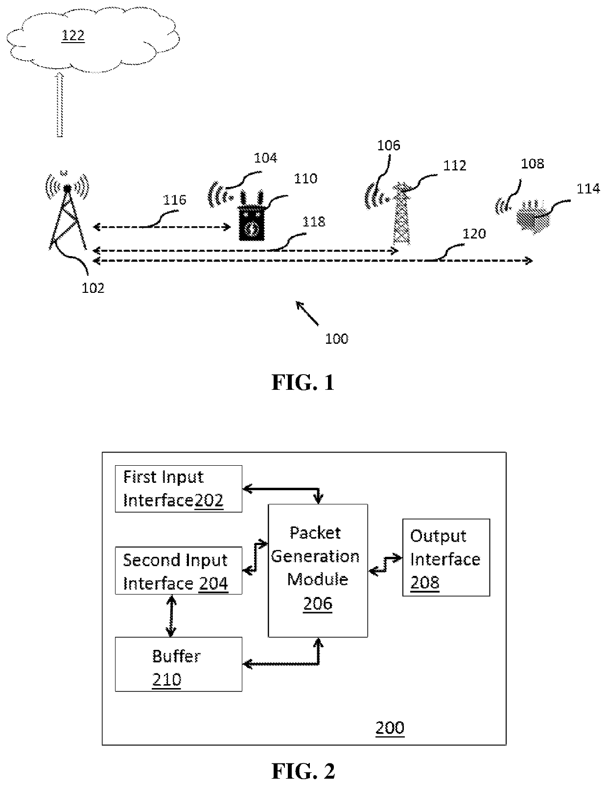
[0025]The present invention provides a method for remote diagnosis and monitoring of field equipment with a diagnostic unit that is associated with the field equipment. The diagnostic unit may be an Intelligent Electronic Device (IED), sensor, or a diagnostic unit provided with a smart circuit breaker. Alternately, the diagnostic unit may be a dedicated unit provided for obtaining and communicating data associated with field equipment such as circuit breaker, wherein such field equipment do not have capability to communicate data over the industrial wireless network. The diagnostic unit is communicatively linked to a field radio device capable of communicating with a base station (BS) over an industrial wireless network. The diagnostic unit obtains diagnostic data, hereinafter referred to as measured data, of the field equipment, which needs to be communicated to the BS via the field radio device. The BS communicates the measured data to a remote server (e.g. IOT application) that i...


PUM


Abstract

Disclosed is a method for remote diagnosis and monitoring of field equipment over an industrial wireless network. A diagnostic unit associated with the field equipment optimizes communication of measured data by a field radio device to a base station. The diagnostic unit is communicatively linked to the field radio device. The measured data is obtained from the field equipment, and a plurality of communication parameters of a communication channel are obtained based on communication from the field radio device. Based on a packet size, a data rate and required application responsiveness, one or more packets comprising the measured data are generated. The generated packets are communicated to the field radio device at selected time intervals based on the packet size, and the application responsiveness, for communication to the base station.

Description

FIELD OF THE INVENTION[0001]The present invention relates generally to condition monitoring of field equipment. More particularly, the present invention relates to remote monitoring and diagnosis of field equipment via an industrial communication network.BACKGROUND OF THE INVENTION[0002]Remote diagnosis and monitoring for electric power systems enables maintenance teams to continuously supervise condition and performance of field equipment. To facilitate remote condition monitoring, diagnostic data, hereinafter referred to as measured data, associated with field equipment of a power system needs to be communicated on a continuous basis to remote control centers. Industrial wireless networks such as a low-power wide area networks (LPWANs) are leveraged to facilitate aforementioned communication between field equipment and remote control centers.[0003]In a typical scenario, the measured data is communicated to a field radio device associated with the field equipment. The field radio d...

Claims


Application Information

Patent Timeline
Patent Type & Authority Applications(United States)
IPC IPC(8): H04Q9/00H04L29/08H04W24/08
CPCH04Q9/00H04Q2209/40H04W24/08H04L67/12H04Q2209/86H04W4/70H04W4/38H04W28/0236H04L67/60
Inventor TANDUR, DEEPAKNATHVARGHESE, ANITHAINGALALLI, ARAVINDKUMAR, SRIJIT
Owner ABB (SCHWEIZ) AG
Why Eureka
Try Eureka