Fixing device and method of manufacturing display panel

a technology of fixing device and display panel, which is applied in the field of display technology, can solve the problems of reducing slicing process risk of fragmentation, and cutting edge of slice, and achieve the effect of improving efficiency and flexibility of production

Active Publication Date: 2021-04-29
TCL CHINA STAR OPTOELECTRONICS TECH CO LTD
View PDF0 Cites 0 Cited by
  • Summary
  • Abstract
  • Description
  • Claims
  • Application Information

AI Technical Summary

Benefits of technology

[0005]The present disclosure provides a display panel and a method of manufacturing a display device, to improve the efficiency and flexibility of production.
[0016]The present disclosure provides a fixing device and a method of manufacturing a display panel, by providing a fixing member on the carrier plate, wherein the fixing member includes at least two opening regions, an area of the opening region is adjustable, the opening region is configured for accommodating the display panel, and since an area of the opening region is adjustable, conveniently fixing multiple sizes of panels, improving the efficiency and flexibility of production.

Problems solved by technology

However, after cutting, the mini LED device are sliced, and an edge of the slice is sharp, and the slicing process risks fragmentation.
However, the slices of different sizes need to be separately fixed, that is, the slices of different sizes cannot be accommodated, which reduces efficiency and flexibility of production.

Method used


Image

  • Fixing device and method of manufacturing display panel
  • Fixing device and method of manufacturing display panel
  • Fixing device and method of manufacturing display panel

Examples


embodiment 1

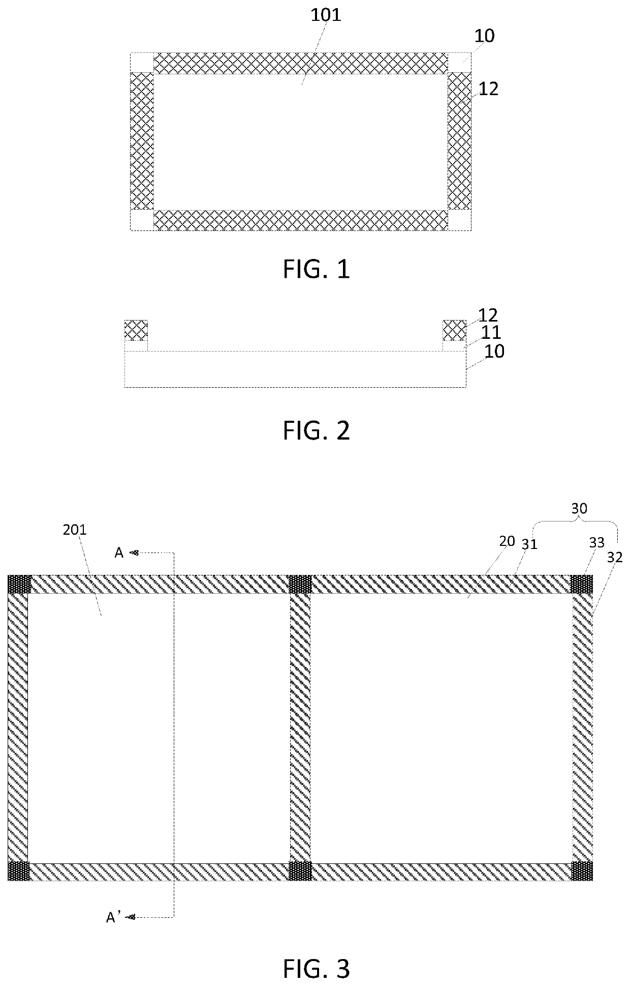
[0028]Please refer from FIG. 3 to FIG. 5, FIG. 3 is a plan view of a fixing device of the present disclosure.

[0029]Combined with FIG. 3 and FIG. 4, the fixing device of the embodiment is used for fixing a display panel, and the fixing device includes: a carrier plate 20.

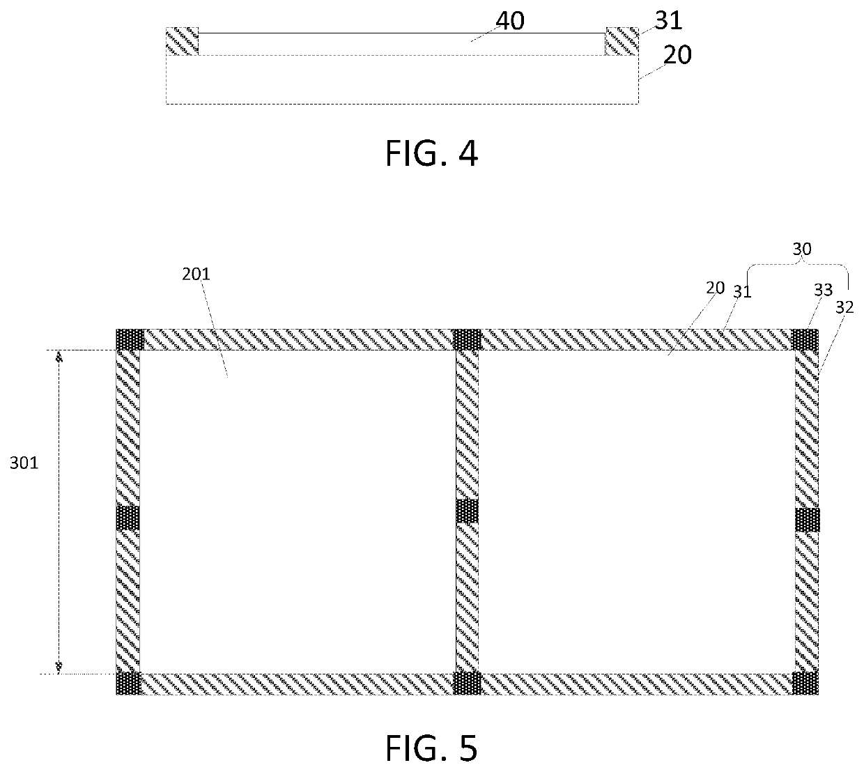
[0030]The carrier plate 20 is provided with a fixing member 30. The fixing member 30 includes two opening regions 201, and an area of the opening region 201 is adjustable, the opening region 201 is configured for accommodating the display panel 40 to define the display panel 40 within the open region 201. It is to be understood that the number of the opening regions 201 is not limited to two. In an embodiment, a thickness of the carrier plate 20 ranging from 1 mm to 2 mm. Of course, the thickness of the carrier plate 20 is not limited thereto. FIG. 4 is a cross-sectional view in the longitudinal direction of FIG. 3, specifically a cross-sectional view taken along line AA′ in FIG. 3.

[0031]In an embodiment, in order t...

second embodiment

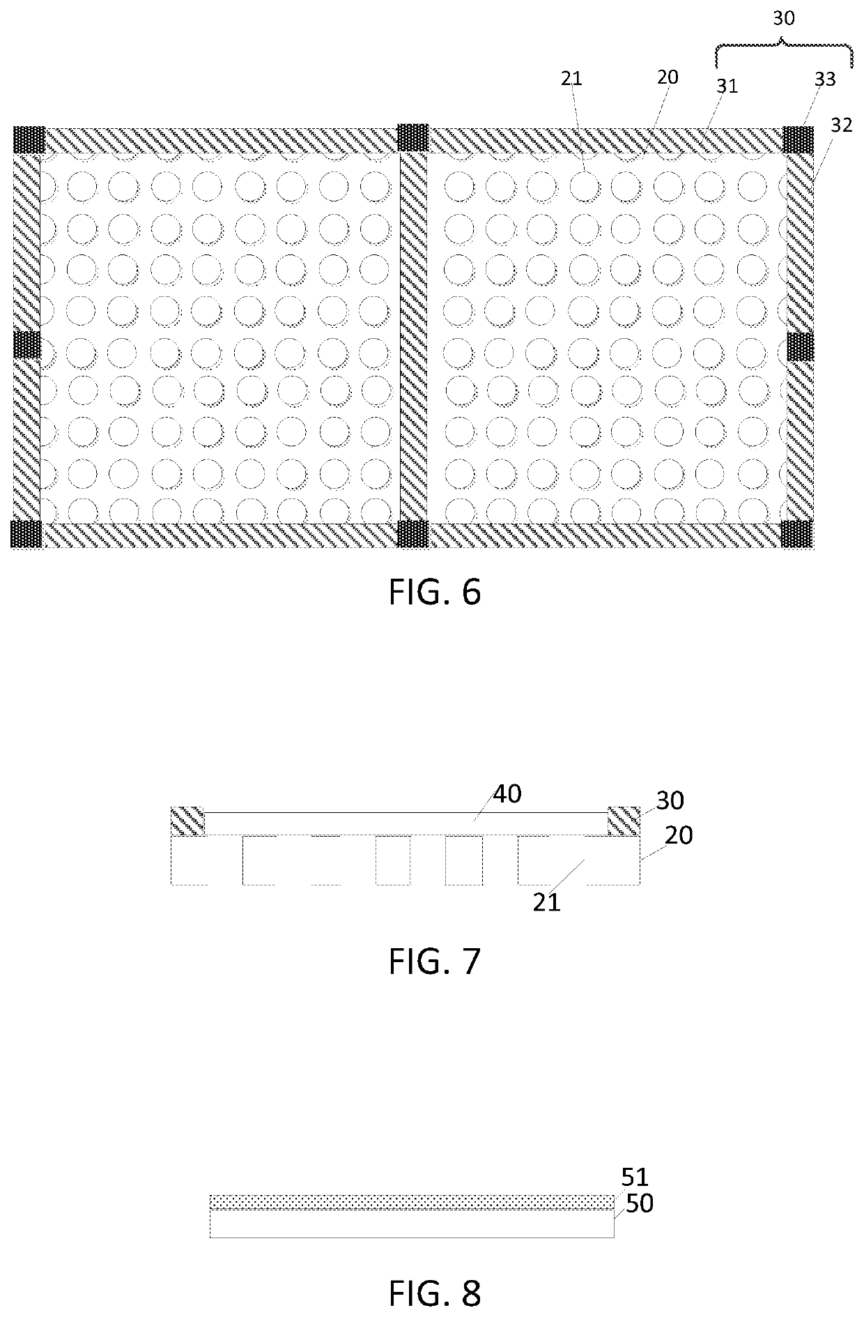
[0035]Please refer to FIG. 6 and FIG. 7, FIG. 6 is a plan view of a fixing device according to the present disclosure.

[0036]As shown in FIG. 6 and FIG. 7, the fixing device of this embodiment differs from the previous embodiment in that the carrier plate 20 is provided with multiple holes 21. Each of the holes 21 is a through hole, and the shape of each of the holes 21 is not limited, which may be a circular, a triangular, or a rectangular shape. The holes 21 may be arranged regularly or in a disorderly arrangement. The multiple holes 21 may be disposed at intervals or may be overlapped.

[0037]Since the carrier plate 20 is provided with a plurality of holes, the residual liquid can be prevented in the subsequent peeling process, and improving the production yield.

[0038]In order to further prevent the residual liquid, a diameter of each of the multiple holes 21 ranges from 5 mm to 10 mm. Of course, the diameter range of the holes is not limited to this.

[0039]The present disclosure als...

first embodiment

[0047]Please refer to FIG. 3, in one embodiment, removing the protective layer 51 on the target display panel 40. It can be understood that the target display panel of this embodiment is equivalent to the display panel of the

[0048]It can be understood that the manufacturing method is also applicable to the second embodiment, and the specific manufacturing process is the same as that, details are not described herein again.

[0049]Since the carrier plate is provided with the fixing member, the fixing member includes at least two opening regions, and the area of the opening region is adjustable; since the area of the opening region is adjustable, conveniently fixing multiple sizes of panels, improving the efficiency and flexibility of production, and reducing the cost of manufacturing.

[0050]The present disclosure provides a fixing device and a method of manufacturing a display panel, by providing a fixing member on the carrier plate, wherein the fixing member includes at least two openi...


PUM


Abstract

The present disclosure provides a fixing device and a method of manufacturing a display panel, the fixing device including a carrier plate provided with a fixing member, wherein the fixing member includes at least two opening regions, an area of the opening region is adjustable, the opening region is configured for accommodating the display panel.

Description

FIELD OF INVENTION[0001]The present disclosure relates to the field of display technology, and more particularly to a fixing device and a method of manufacturing a display panel.BACKGROUND OF INVENTION[0002]Currently, display panels are diversified, wherein the resolution and color of mini LED devices are closer to organic light emitting diode (OLED) displays. Mini LED devices are superior to liquid crystal displays (LCDs), and having lower power consumption, being lighter and thinner. However, after cutting, the mini LED device are sliced, and an edge of the slice is sharp, and the slicing process risks fragmentation. Therefore, it is necessary to perform edging after cutting to increase the strength and reduce the risk of fragmentation.[0003]In order to protect the surface of the substrate, the substrate is coated with a protective layer, and after the edging, the protective layer is removed by a stripper. However, in the stripping process, the slice needs to be fixed. As shown in...

Claims


Application Information

Patent Timeline
Patent Type & Authority Applications(United States)
IPC IPC(8): H01L21/673H01L23/00
CPCH01L21/6734H01L23/562
Inventor CHEN, HAO
Owner TCL CHINA STAR OPTOELECTRONICS TECH CO LTD
Why Eureka
Try Eureka