Hand tool with self-resilient handle

a hand tool and handle technology, applied in the direction of pliers, line/current collector details, electrical equipment, etc., can solve the problems of many parts and complex construction of the hand tool

Active Publication Date: 2022-10-11
PRESSMASTER
View PDF11 Cites 1 Cited by
  • Summary
  • Abstract
  • Description
  • Claims
  • Application Information

AI Technical Summary

Benefits of technology

[0005]It is an object of the present invention to provide a hand tool comprising relatively few components that allows objects of different sizes to be operated with varying operating forces.
[0007]The fact that the first handle, comprising both the handle and a jaw, comprises a resilient portion has the advantage that no separate resilient system is needed. This has the advantage that the hand tool 1 will be less complex and more durable.

Problems solved by technology

A drawback of the construction of the hand tool in U.S. Pat. No. 6,612,206 B1 is that its construction is rather complex and includes many parts.

Method used


Image

  • Hand tool with self-resilient handle
  • Hand tool with self-resilient handle
  • Hand tool with self-resilient handle

Examples


Embodiment Construction

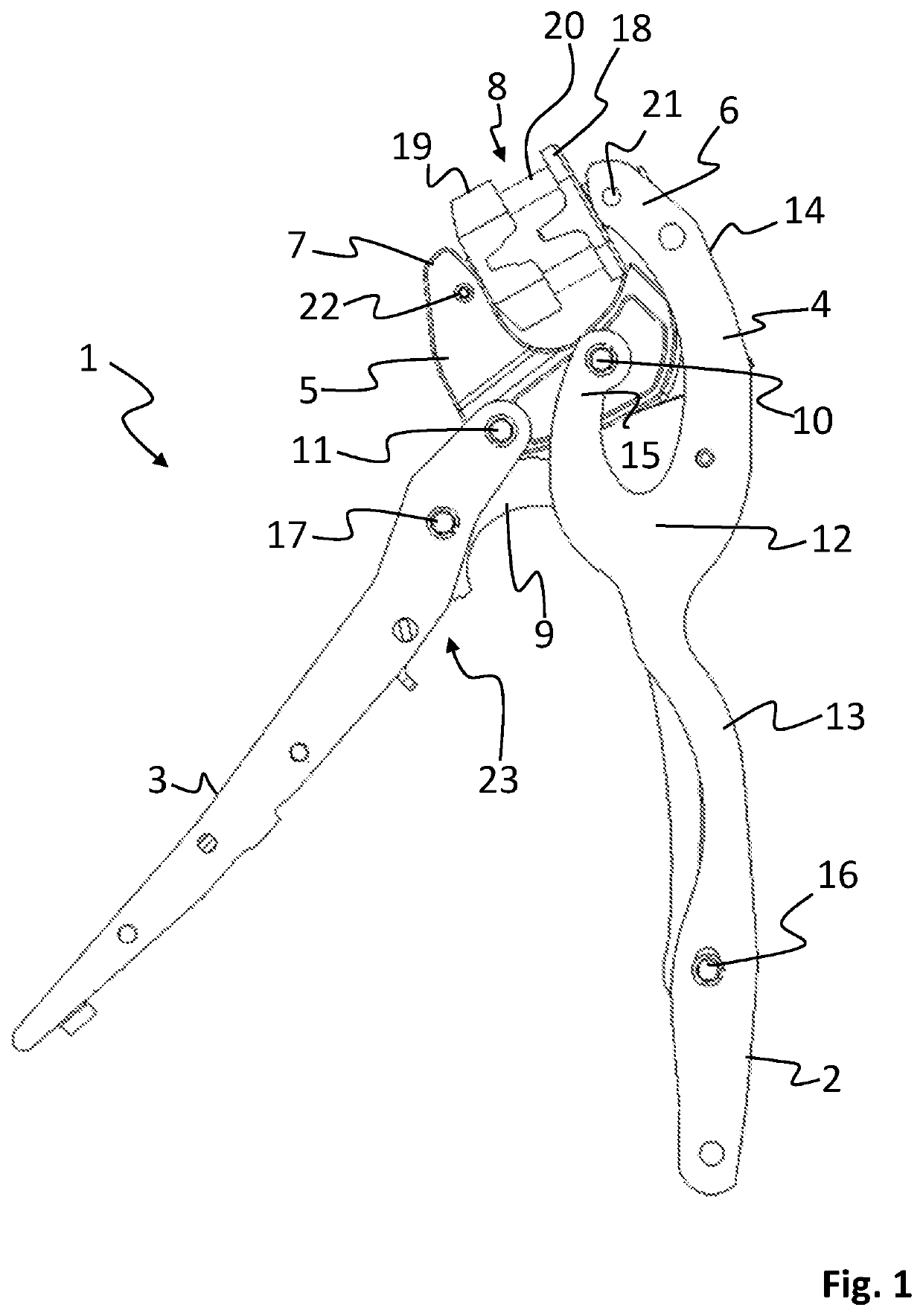
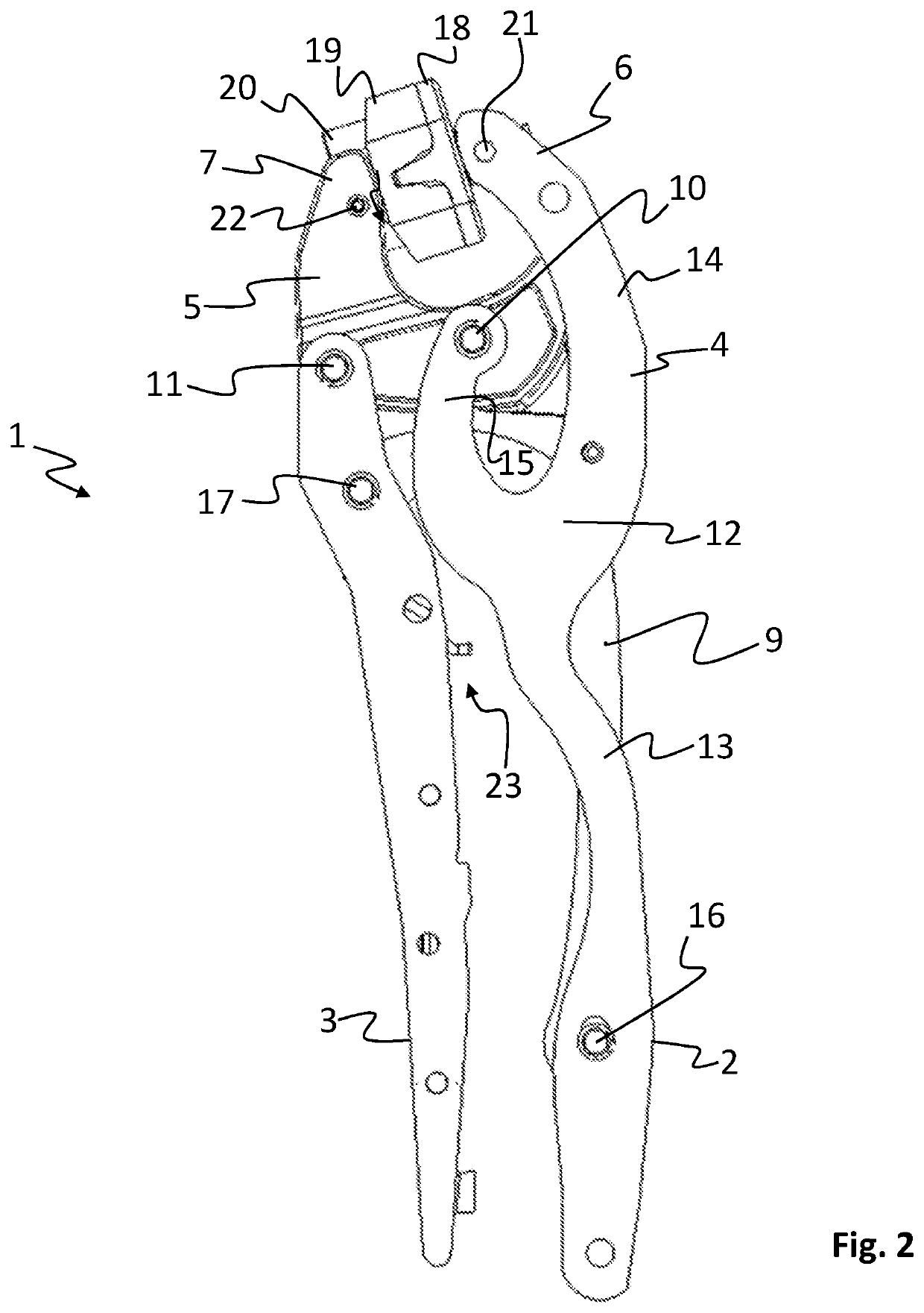
[0020]In FIG. 1 a hand tool 1 in accordance with a first embodiment of the invention is shown in an open position, and in FIG. 2 the same hand tool 1 is shown in a closed position.

[0021]The hand tool 1 comprises a first handle 2 and a second handle 3, which are pivotally arranged with respect to each other by means of a connecting linkage. A first jaw 4 is fixed to the first handle 2, and preferably, the first jaw 4 and the first handle 2 are formed as one integrated part. The first jaw 4 comprises a first crimp portion 6, which is located at an upper end of the first jaw 4.

[0022]The hand tool 1 also comprises a second jaw 5 comprising a second crimp portion 7, wherein the first and second crimp portions 6 and 7 are arranged to be moved towards each other by actuation of the first and a second handle 2 and 3, so as to close a crimp opening 8 formed between said first and second crimp portions 6 and 7. In FIG. 1, the handles 2 and 3 are in an open position, separated from each other,...


PUM


Abstract

A hand tool (1) comprising a first handle (2) and a second handle (3), which are pivotally arranged with respect to each other, a first jaw (4) that is fixed to said first handle (2), the first jaw (4) comprising a first crimp portion (6), and a second jaw (5) comprising a second crimp portion (7), wherein the first and second crimp portions (6,7) are arranged to be moved towards each other by actuation of the first and a second handle (2,3), so as to close a crimp opening (8) formed between said first and second crimp portions (6,7). The second jaw (5) is pivotally arranged with respect to the first handle (2) around a first pivot point (10), and with respect to the second handle (3) around a second pivot point (11) arranged at an upper end of said second handle (3), wherein the first handle (2) comprises a first resilient portion (12) between the first crimp portion (6) and the first pivot point (10), allowing the first crimp portion (6) to flex with respect to the first pivot point (10).

Description

TECHNICAL FIELD[0001]The invention relates to a hand tool with a self-resilient handle. Specifically, the invention relates to such a hand tool where one of the handles is configured to involve an inherent controlled resiliency that allows for objects of different sizes to be crimped in a crimp opening of the tool.BACKGROUND[0002]In many applications where precision hand tools, such as crimping pliers or the like are utilized, it is desired to manipulate objects of different sizes in the operating area of the tool. For crimping pliers where an object, such as a connector, is crimped between a male and a female tool a larger force will need to be applied to crimp a larger object compared to a relatively smaller object.[0003]In U.S. Pat. No. 6,612,206 B1 a hand tool is disclosed which comprises a resilient connecting element that is arranged between a first handle and an opposite jaw on a hand tool. The resilient connecting element functions to push the handles into an open position a...

Claims


Application Information

Patent Timeline
Patent Type & Authority Patents(United States)
IPC IPC(8): B25B27/14B25B7/14
CPCB25B27/146B25B7/14B25B7/12H01R43/042
Inventor ULLBORS, DANIEL
Owner PRESSMASTER
Why Eureka
Try Eureka