Eureka AIR delivers breakthrough ideas for toughest innovation challenges, trusted by R&D personnel around the world.

Scroll heating device

a heating device and roller technology, applied in lighting and heating apparatus, combustion types, combustion using catalytic materials, etc., can solve the problems of affecting the mechanical structure and weight of the heat exchanger and affecting the combustion efficiency of the heat source for use with a stirling engin

Active Publication Date: 2022-10-25
NAT CHENG KUNG UNIV
View PDF33 Cites 0 Cited by
  • Summary
  • Abstract
  • Description
  • Claims
  • Application Information

AI Technical Summary

Benefits of technology

[0019]The present invention can produce the following advantageous effects: A gas moving through the first channel to the reaction region can be preheated by the exhaust in the immediately adjacent turns of the second channel that flank each but the outermost turn of the first channel. In addition, the first channel, which gradually widens toward the center of the base, allows a gas flowing into the first channel to flow toward the reaction region at a progressively slower rate and then enter the reaction region slowly through the gradually widening first channel, thereby increasing the time for which the gas stays and burns in the reaction region. Moreover, when the exhaust moves through the second channel toward the gas outlet, the gas that is about to enter the reaction region is preheated by the exhaust. Thus, the scroll heating device transmits and retains heat and can reduce unnecessary heat dissipation and exergy destruction, allowing chemical energy to be converted into thermal energy stably. Also, the scroll heating device has no limitation on the type of the fuel gas used, meaning the scroll heating device can work with, and thus remove the limitations conventionally imposed on, low-heat-value gases that are difficult to burn directly, and this makes it possible to reuse energy effectively.
: A gas moving through the first channel to the reaction region can be preheated by the exhaust in the immediately adjacent turns of the second channel that flank each but the outermost turn of the first channel. In addition, the first channel, which gradually widens toward the center of the base, allows a gas flowing into the first channel to flow toward the reaction region at a progressively slower rate and then enter the reaction region slowly through the gradually widening first channel, thereby increasing the time for which the gas stays and burns in the reaction region. Moreover, when the exhaust moves through the second channel toward the gas outlet, the gas that is about to enter the reaction region is preheated by the exhaust. Thus, the scroll heating device transmits and retains heat and can reduce unnecessary heat dissipation and exergy destruction, allowing chemical energy to be converted into thermal energy stably. Also, the scroll heating device has no limitation on the type of the fuel gas used, meaning the scroll heating device can work with, and thus remove the limitations conventionally imposed on, low-heat-value gases that are difficult to burn directly, and this makes it possible to reuse energy effectively.

Problems solved by technology

However, the combustion efficiency of a heat source for use with a Stirling engine tends to be compromised by the dissipation of hot air during the heating process, and the pressure on the internal structure of the heat source varies greatly during the same process.
Moreover, there are limitations on the mechanical structure and weight of a heat exchanger for use with a Stirling engine.
A heat exchanger with a thin base has relatively high thermal conduction efficiency but relatively low structural strength.
A heat exchanger with a thick base is enhanced in structural strength but has relatively low thermal conduction efficiency.
While thermal conduction efficiency can be increased by way of heat pipes, the heat pipes result in an increase in cost as well as bulkiness, both drawbacks demanding improvement.
Furthermore, combustion through catalyst-assisted low-temperature oxidation has been a research topic in the combustion science for many years, the greatest challenge being to oxidize a low-level fuel completely so as to obtain chemical energy therefrom.

Method used


Image

  • Scroll heating device
  • Scroll heating device
  • Scroll heating device

Examples


Embodiment Construction

[0027]The detailed description and preferred embodiments of the invention will be set forth in the following content, and provided for people skilled in the art to understand the characteristics of the invention.

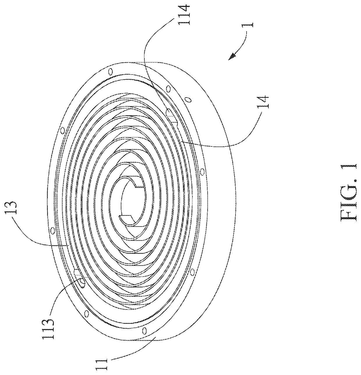
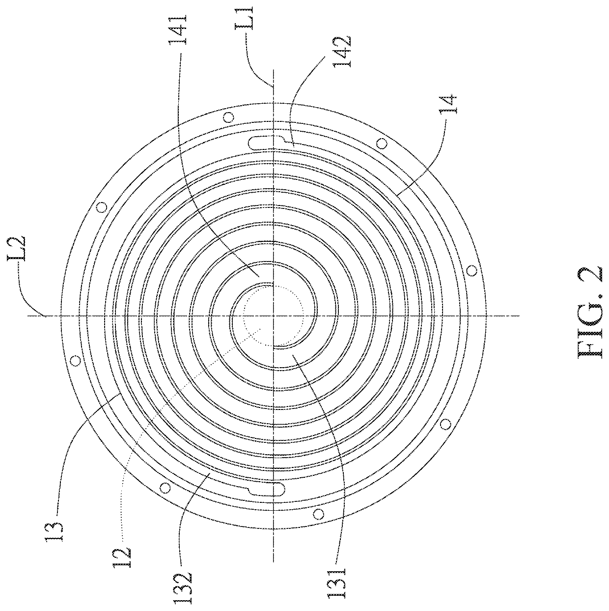
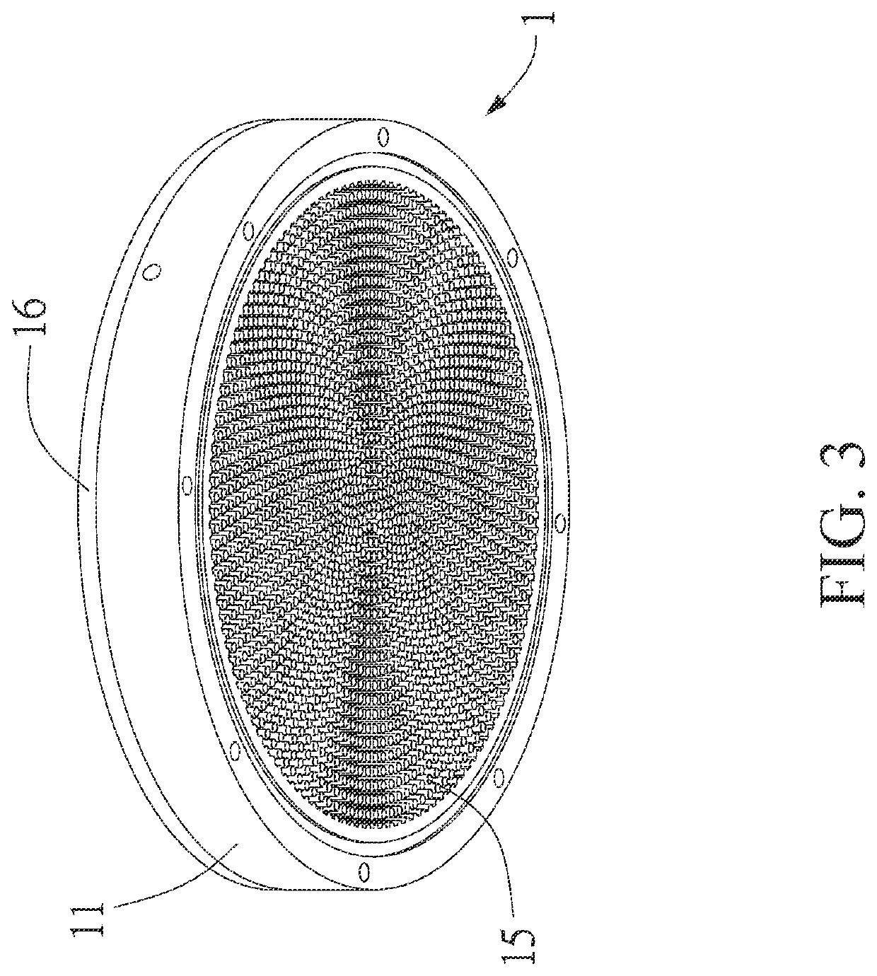
[0028]Referring to FIGS. 1-3, the scroll heating device 1 according to an embodiment of the present invention includes a base 11, a reaction region 12, a first channel 13, a second channel 14, a plurality of pin fins 15, and a cover 16. The scroll heating device 1 is adapted to be coupled to the heating end of a Stirling engine 9 (see FIG. 6).

[0029]The scroll heating device 1 is made of a thermally conductive material. The thermally conductive material may be one or a combination selected from the group consisting of a metal, a metal alloy (preferably stainless steel, an aluminum alloy, etc.), and ceramic, and is preferably resistant to temperatures as high as 933 K. Due to its good thermal conductivity, the thermally conductive material can conduct heat to the Stirling engi...


PUM


Abstract

A scroll heating device includes a base, a reaction region, and a first and a second channel. The reaction region is at the center of the base. The two channels are located on the base and extend spirally from the reaction region toward the periphery of the base. The width of each channel is gradually reduced as the channel extends from adjacent to the center of the base toward the periphery of the base. The first channel allows a gas that flows into the first channel through the periphery of the base toward the center of the base to flow toward the reaction region at a progressively slower rate, enter the reaction region slowly through the gradually widening first channel, and therefore stay in the reaction region for longer. The combusted exhaust enters the second channel from adjacent to the center of the base and exits through the periphery of the base.

Description

CROSS REFERENCE[0001]This non-provisional application claims the benefit of American Provisional Application No. 63 / 108,452, filed on Nov. 2, 2020, the contents thereof are incorporated by reference herein.BACKGROUND OF THE INVENTION1. Technical Field[0002]The present invention relates to a heating device and more particularly to a scroll heating device.2. Description of Related Art[0003]A Stirling engine is a highly efficient external combustion energy converting device and can be driven into operation by a heat source (such as solar energy, waste heat, nuclear raw material, cow manure, propane, natural gas, biogas (methane), butane, petroleum, or other fuels) as long as the temperature of the heat source is high enough. Unlike such internal combustion engines as gasoline engines and diesel engines, which require the use of specific fuels, Stirling engines need less maintenance and are more efficient, quieter, and more reliable.[0004]The conventional Stirling engines absorb the hea...

Claims


Application Information

Patent Timeline
Patent Type & Authority Patents(United States)
IPC IPC(8): F02G1/055F23C3/00F23L15/04F23C13/08
CPCF02G1/055F23C3/00F23L15/04F02G2254/15F02G2254/18F02G2254/70F02G2258/10F23C13/08F23C2900/13001F23C2900/99011F23N2221/08
Inventor WU, CHIH-YUNGCHEN, WEN-LIH
Owner NAT CHENG KUNG UNIV
Why Eureka
Eureka Blog
Learn More