Pneumatic tire with rim protector including plurality of recesses

a technology of pneumatic tires and rim protectors, applied in the field of pneumatic tires, to achieve the effect of suppressing the decrease in rigidity

Active Publication Date: 2022-11-08
TOYO TIRE & RUBBER CO LTD
View PDF20 Cites 0 Cited by
  • Summary
  • Abstract
  • Description
  • Claims
  • Application Information

AI Technical Summary

Benefits of technology

[0012]In accordance with this constitution, because not less than two recesses are arranged with spaces therebetween in the tire circumferential direction at rim protector which constitutes an annular protrusion, projections will be formed between pairs of mutually adjacent recesses, and it will be possible to suppress decrease in rigidity more than would be the case with a structure in which pairs of mutually adjacent recesses are arranged without gaps therebetween in the tire circumferential direction. And yet, because mutually adjacent pair(s) of recesses are in positional relationship(s) such that the members of the pair partially overlap as seen when projected onto a virtual plane perpendicular to the tire radial direction, thickened region(s) will be present at said overlapping portion(s), permitting decrease in locations at which only a thinned region is present as viewed in the tire radial direction, and making it possible to decrease locations at which strain is concentrated and to cause strain to be distributed.

Problems solved by technology

With structures in which there is a rim protector that has recesses which extend continuously in the tire circumferential direction, because thinned regions will be present in continuous fashion in the tire circumferential direction due to the recesses, rigidity will be insufficient and the tire will be susceptible to flexing in the tire radial direction.
Structures in which there is a rim protector that has a plurality of recesses which are arranged continuously without gaps therebetween in the tire circumferential direction will likewise have insufficient rigidity.

Method used


Image

  • Pneumatic tire with rim protector including plurality of recesses
  • Pneumatic tire with rim protector including plurality of recesses
  • Pneumatic tire with rim protector including plurality of recesses

Examples


first embodiment

[0019]Below, a pneumatic tire in accordance with a first embodiment of the present disclosure will be described with reference to the drawings.

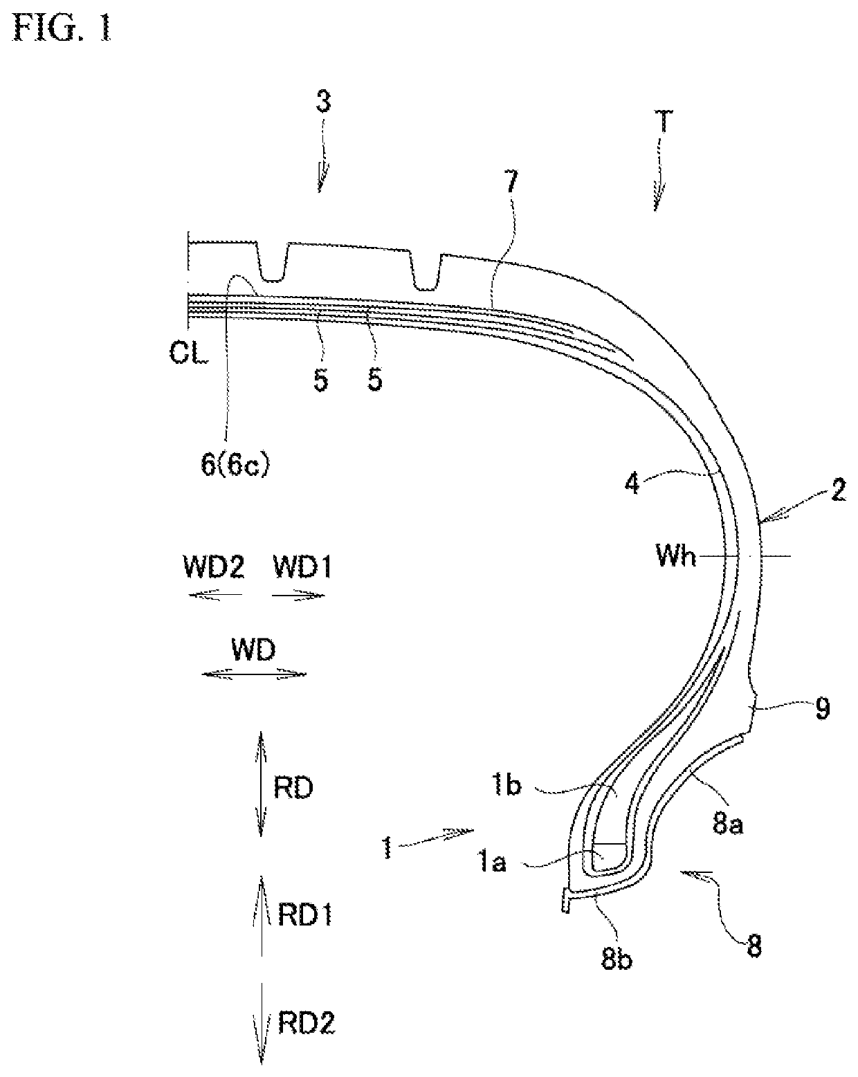
[0020]As shown in FIG. 1, pneumatic tire T is provided with a pair of bead regions 1; sidewall regions 2 which extend toward the exterior RD1 in the tire radial direction from the respective bead regions 1; and tread region 3 which mutually connects the ends toward the exterior RD1 in the tire radial direction of the sidewall regions 2. Arranged at bead region 1 are annular bead core 1a at which steel wire or other such convergent body is coated with rubber, and bead filler 1b which comprises hard rubber. Bead region 1 is mounted on bead sheet 8b of rim 8, and provided that the air pressure is as it should be (e.g., air pressure as determined by JATMA)—is fitted in appropriate fashion to rim flange 8a by virtue of the tire internal pressure, such that the tire is made to engage with rim 8.

[0021]Furthermore, this tire is provided with toroidal...

second embodiment

[0027]Description will be carried out with respect to a tire in accordance with a second embodiment.

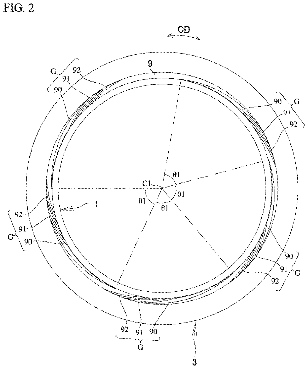
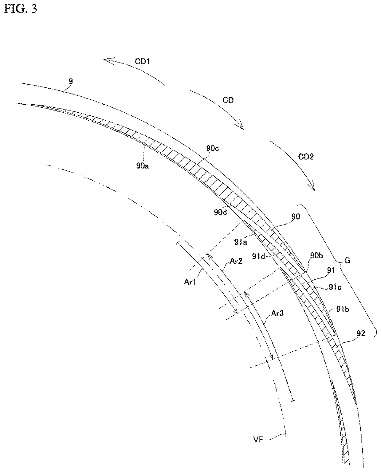
[0028]As shown in FIG. 4 and FIG. 5, rim protector 9 has not less than two recesses 190, 191, 192, 193, 194 that extend toward the tread region from a location toward the bead region in such fashion as to be directed toward a location in the second direction CD2 from a location in the first direction CD1 in the tire circumferential direction CD. These not less than two recesses 190, 191, 192, 193, 194 are arranged with spaces therebetween in the tire circumferential direction CD. Whereas there are five recesses 190, 191, 192, 193, 194 in the example shown in FIG. 4 and FIG. 5, there is no limitation with respect thereto. It is sufficient that there be not less than two recesses. It is preferred that maximum depth D1 of recesses 190, 191, 192, 193, 194 be not less than 0.5 mm and not greater than 3.0 mm. As shown in FIG. 5, a mutually adjacent pair of recesses (190, 191) (191, 192) (19...


PUM


Abstract

A tire has a rim protector which is formed at a sidewall and which constitutes an annular protrusion that extends in a tire circumferential direction. The rim protector has not less than two recesses that extend toward the tread region from a location toward the bead region in such fashion as to be directed toward a location in a second direction from a location in a first direction in the tire circumferential direction, the not less than two recesses being arranged with spaces therebetween in the tire circumferential direction. A mutually adjacent pair of recesses among the not less than two recesses are in a positional relationship such that they partially overlap as seen when projected onto a virtual plane perpendicular to a tire radial direction.

Description

BACKGROUND OF THE INVENTIONField of the Invention[0001]The present disclosure relates to a pneumatic tire.Description of the Related Art[0002]A pneumatic tire has a tread, and beads, and has sidewalls arranged between the tread and the beads. There are pneumatic tires in which a rim protector is formed along the entire circumference at a portion of the sidewall that is located toward the exterior in the tire radial direction from the region contacted by the rim flange. It is often the case that the cross-sectional shape of the rim protector is trapezoidal or triangular, being the same every here along the entire circumference of the sidewall.[0003]Japanese Patent Application Publication Kokai No. 2002-59712 discloses that arrangement of a plurality of recesses with spaces therebetween in the tire circumferential direction at a rim protector reduces the thickness of the rim protector and suppresses generation of heat, and that the recesses also cause increase in surface area and impr...

Claims


Application Information

Patent Timeline
Patent Type & Authority Patents(United States)
IPC IPC(8): B60C13/02B60C15/024
CPCB60C15/0242B60C13/02
Inventor KUWANO, SHINGOYASUNAGA, TOSHIKAZU
Owner TOYO TIRE & RUBBER CO LTD
Why Eureka
Try Eureka