Inrush current limiter and system including the same

Active Publication Date: 2022-11-08
SAMSUNG SDI CO LTD
View PDF8 Cites 0 Cited by
  • Summary
  • Abstract
  • Description
  • Claims
  • Application Information

AI Technical Summary

Benefits of technology

[0007]Issues to be solved through embodiments of the present disclosure may relate to an inrush current limiter, and to a system including the same, which may enable normal operation of the system even in an EMC test environment by improving an operation voltage range of an inrush current limiting circuit.
[0023]According to the disclosed embodiments, the operation voltage range of the inrush current limiting circuit is improved to enable normal operation of the system even in an EMC test environment.

Problems solved by technology

The inrush current may be suitable limited because the inrush current may otherwise cause permanent damage, faults, or abnormal operation of the system.
However, in the case of the conventional inrush current limiter designed for a high voltage (HV) system, when the supply voltage is lowered below a certain level, there may be a problem in which an erroneous operation is caused, and thus there may be room for improvement.

Method used


Image

  • Inrush current limiter and system including the same
  • Inrush current limiter and system including the same
  • Inrush current limiter and system including the same

Examples


Embodiment Construction

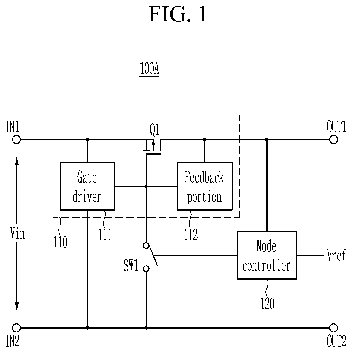
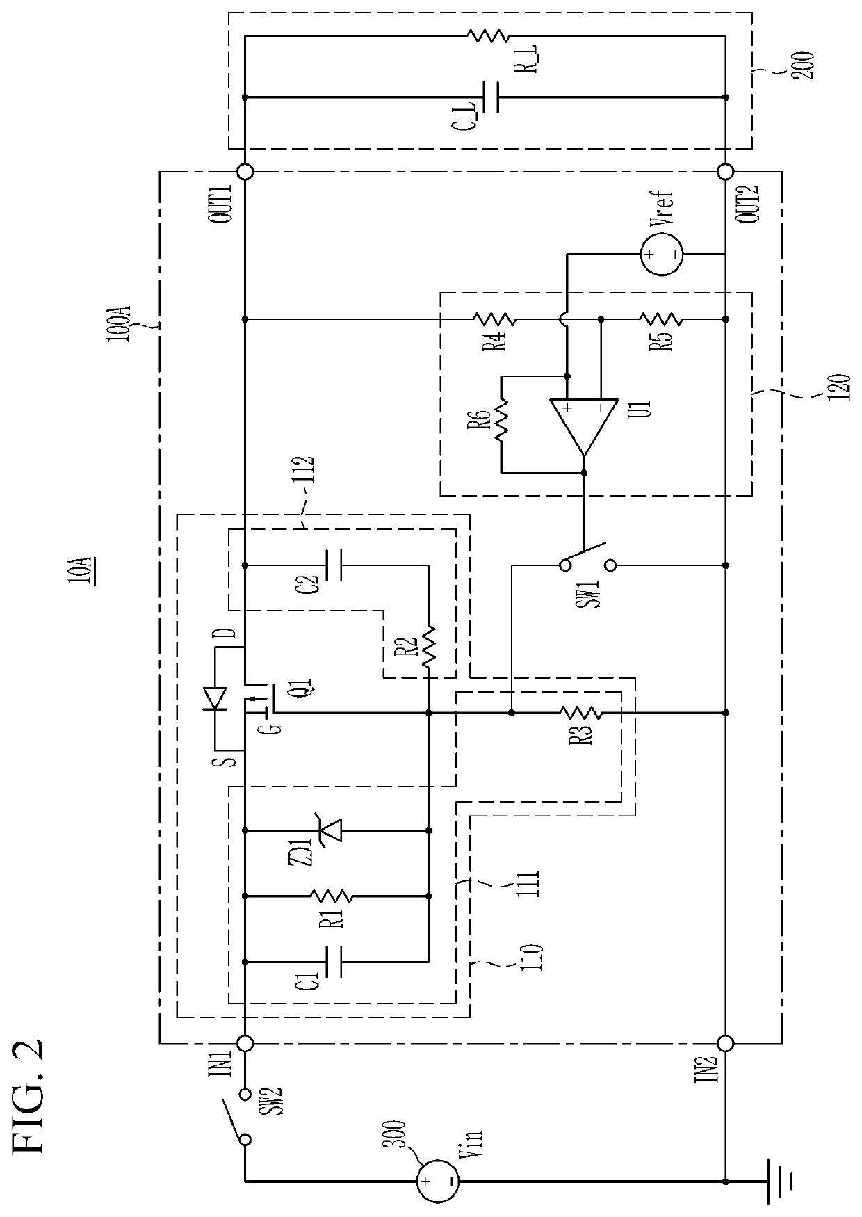
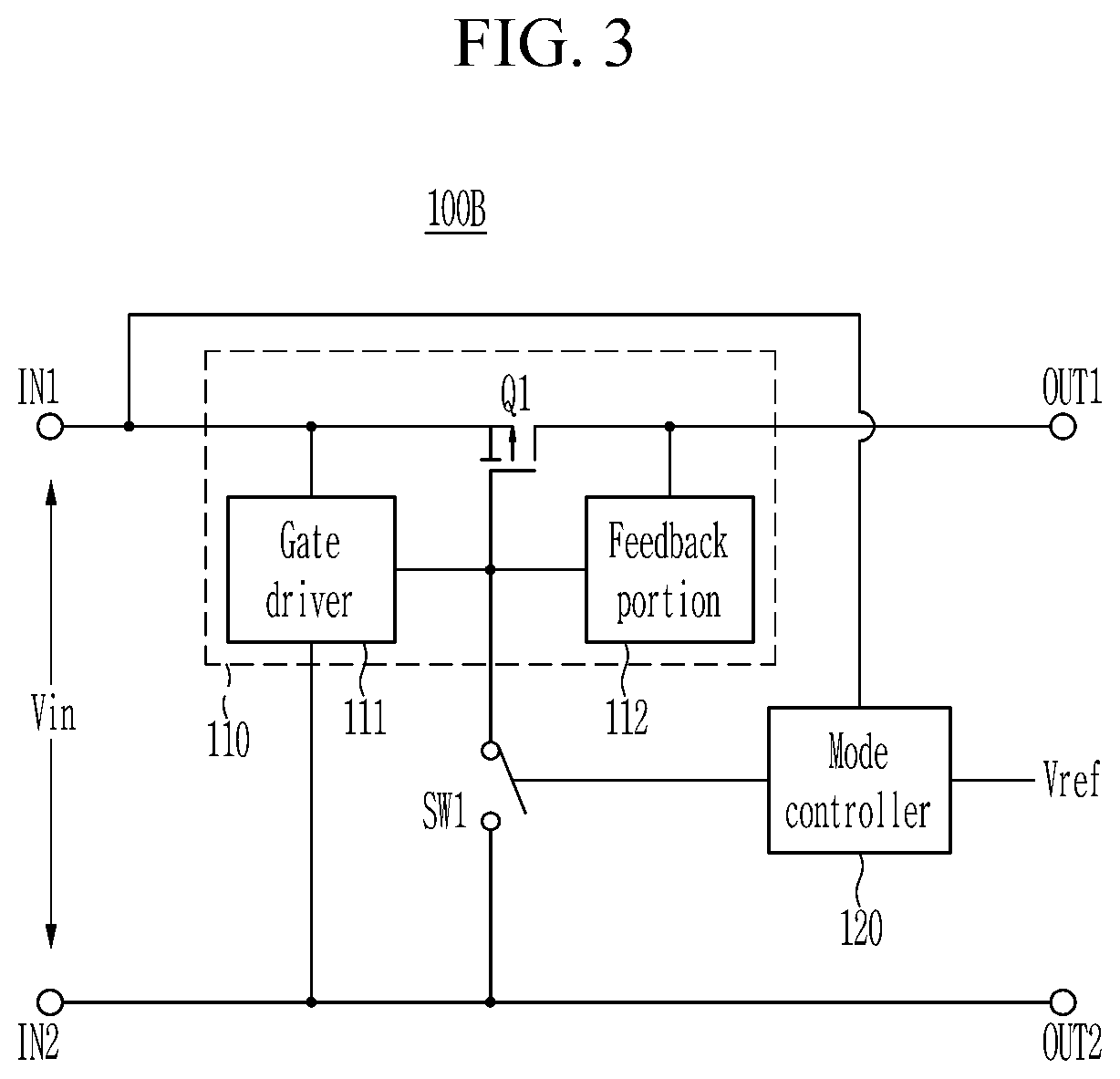
[0029]Aspects of some embodiments of the present disclosure and methods of accomplishing the same may be understood more readily by reference to the detailed description of embodiments and the accompanying drawings. Hereinafter, embodiments will be described in more detail with reference to the accompanying drawings. The described embodiments, however, may be embodied in various different forms, and should not be construed as being limited to only the illustrated embodiments herein. Rather, these embodiments are provided as examples so that this disclosure will be thorough and complete, and will fully convey the aspects of the present disclosure to those skilled in the art. Accordingly, processes, elements, and techniques that are not necessary to those having ordinary skill in the art for a complete understanding of the aspects of the present disclosure may not be described.

[0030]Unless otherwise noted, like reference numerals, characters, or combinations thereof denote like elemen...


PUM


Abstract

Provided is an inrush current limiter and a system including the same, the inrush current limiter including first and second input nodes for receiving an input voltage from a power source, a first output node and a second output node for being connected with a load, an inrush-current-limiting portion including a transistor connected between the first input node and the first output node, and for turning on the transistor when a voltage level of the input voltage is higher than a first level, and for limiting an inrush current by controlling time until the transistor is turned on after application of the input voltage, a switch connected between a control terminal of the transistor and the second input node, and a mode controller for turning on the switch when the voltage level of the input voltage is lower than a second level that is lower than the first level.

Description

CROSS-REFERENCE TO RELATED APPLICATION[0001]This application claims priority to, and the benefit of, Korean Patent Application No. 10-2020-0064398 filed in the Korean Intellectual Property Office on May 28, 2020, the entire contents of which are incorporated herein by reference.BACKGROUND1. Field[0002]Embodiments of the present disclosure relate to an inrush current limiter, and a system including the same.2. Description of the Related Art[0003]Inrush current is a transient phenomenon that occurs depending on the size of a load when an input voltage is applied in an electrical / electronic system. The inrush current may be suitable limited because the inrush current may otherwise cause permanent damage, faults, or abnormal operation of the system. In general, a battery management system (BMS) applied to a battery pack is also applied with a technology for limiting an inrush current.[0004]Meanwhile, in the case of vehicles, vehicles being one of the representative systems in which a ba...

Claims


Application Information

Patent Timeline
Patent Type & Authority Patents(United States)
IPC IPC(8): H02H9/00H03K17/687
CPCH02H9/001H03K17/687
Inventor KIM, KEUNYOUNGKIM, HYUNPARK, JAESOONCHOI, SUNHO
Owner SAMSUNG SDI CO LTD
Why Eureka
Try Eureka