
Control of activation threshold for vehicle safety systems

a vehicle safety and activation threshold technology, applied in the direction of brake systems, instruments, transportation and packaging, etc., can solve problems such as poor visibility

Active Publication Date: 2022-11-15
ZENUITY AB
View PDF21 Cites 0 Cited by
  • Summary
  • Abstract
  • Description
  • Claims
  • Application Information

AI Technical Summary

Benefits of technology

[0007]It is therefore an object of the present invention to provide a method for controlling an activation threshold of a safety system of a vehicle, a non-transitory computer-readable storage medium, a vehicle control system, a vehicle, and a vehicle management system, which alleviate all or at least some of the drawbacks of presently known systems.
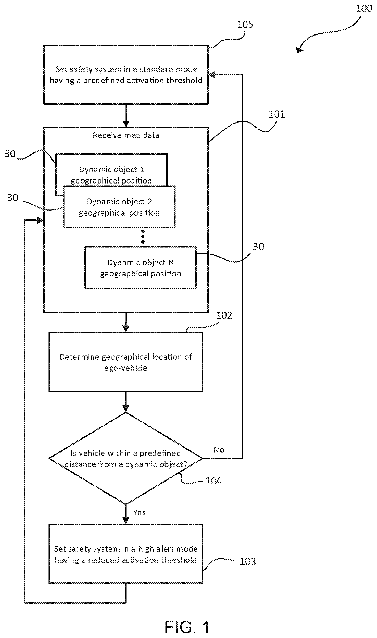
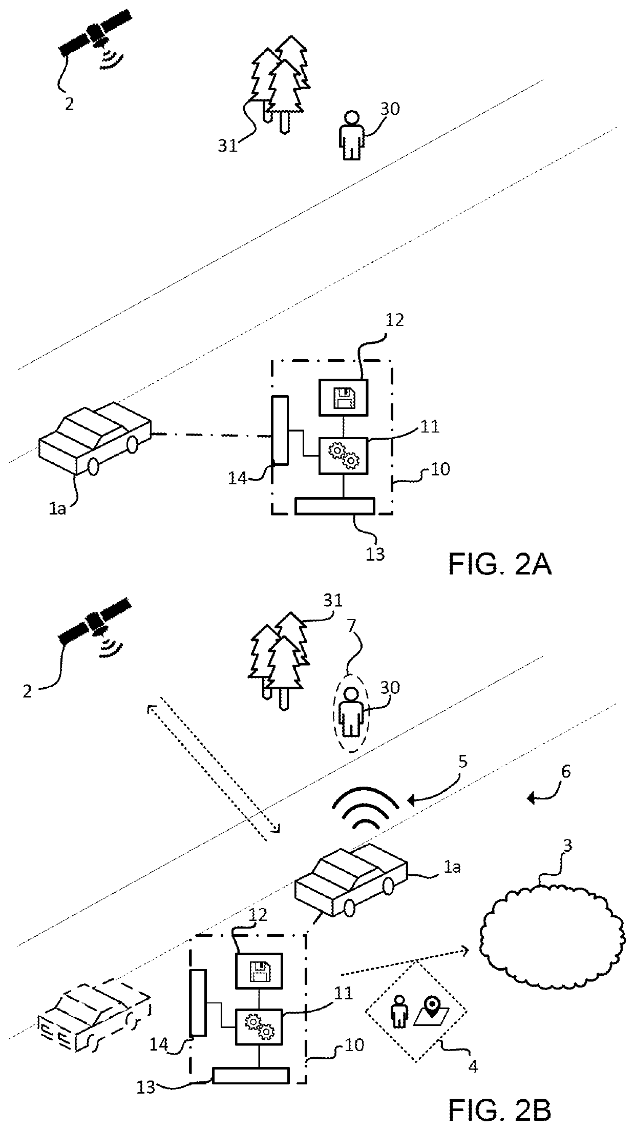
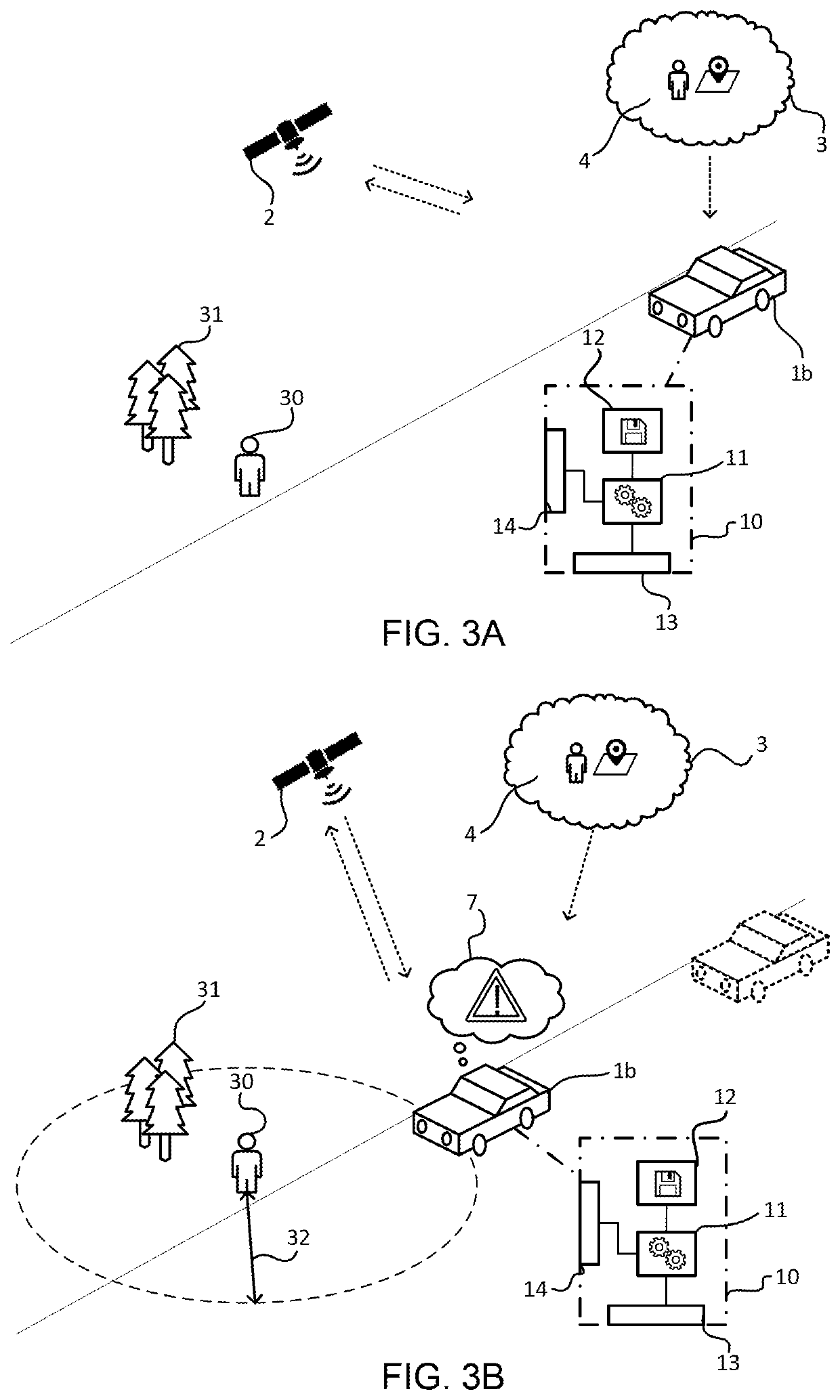
[0009]According to a first aspect of the present invention, there is provided a method for controlling an activation threshold of a safety system of a vehicle. The method comprises receiving map data from a remote data repository, the map data comprising a geographical location of a dynamic object located in a surrounding environment (may also be referred to as surrounding area) of an expected path of the vehicle, and determining a geographical location of the vehicle by means of a localization system of the vehicle. The method further comprises lowering an activation threshold value of the safety system when the geographical location of the vehicle is within a predefined distance from the dynamic object. The presented method provides for an efficient means for preparing e.g. an emergency brake assist system of a vehicle in potentially critical situations.
[0010]The present invention is at least partly based on the realization that real-time map data can be used as an additional “sensor input” in order to detect whether or not the vehicle is located in a potentially critical situation. Thus, instead of just relying on the ego-vehicle's perception system and associated sensor data, or determining from static map data that the ego-vehicle is located in some general critical area, the proposed method utilizes other vehicles' sensor data to adequately prepare one or more safety systems of the vehicle in order to mitigate collision risks. Particularly, on small and windy country roads where visibility may be poor (high number of corners and elevations).
[0011]The predefined distance may for example be within a 500 m radius of the last known geographical location of the dynamic object. However, the predefined distance may also be dynamically determined based on the type of dynamic object. For example, a cyclist may be associated with a larger predefined distance than a pedestrian. This is because a cyclist can be assumed to move at a faster speed wherefore an increase of the predefined distance (safety radius) can account for the greater movement speed.
[0012]Further, according to an exemplary embodiment, the dynamic object is a first dynamic object the method further comprises determining a position, relative to the vehicle, of the second dynamic object in a surrounding environment of the vehicle, determining a geographical location of the second dynamic object in the surrounding environment of the vehicle based on the determined position of the second dynamic object and the determined geographical location of the vehicle, and transmitting wireless data packets comprising information about the geographical location of the second dynamic object to the remote data repository. Thus, the ego-vehicle can also be utilized as part of a network of map data providers. Moreover, this allows the map data to be continuously updated of the movement of the dynamic object(s), further increasing the accuracy of the method.

Problems solved by technology

Particularly, on small and windy country roads where visibility may be poor (high number of corners and elevations).

Method used


Image

  • Control of activation threshold for vehicle safety systems
  • Control of activation threshold for vehicle safety systems
  • Control of activation threshold for vehicle safety systems

Examples


Embodiment Construction

[0025]Those skilled in the art will appreciate that the steps, services and functions explained herein may be implemented using individual hardware circuitry, using software functioning in conjunction with a programmed microprocessor or general purpose computer, using one or more Application Specific Integrated Circuits (ASICs) and / or using one or more Digital Signal Processors (DSPs). It will also be appreciated that when the present disclosure is described in terms of a method, it may also be embodied in one or more processors and one or more memories coupled to the one or more processors, wherein the one or more memories store one or more programs that perform the steps, services and functions disclosed herein when executed by the one or more processors.

[0026]In the following description of exemplary embodiments, the same reference numerals denote the same or analogous components.

[0027]Even though the following discussion is mainly focused on a vehicle safety system in the form o...


PUM


Abstract

There is presented a method for controlling an activation threshold of a safety system of a vehicle. The method comprises receiving map data from a remote data repository, said map data comprising a geographical location of a dynamic object located in a surrounding area of an expected path of the vehicle, determining a geographical location of the vehicle by means of a localization system of the vehicle, and lowering an activation threshold value of the safety system when the geographical location of the vehicle is within a predefined distance from the dynamic object. The presented method provides for an efficient means for preparing e.g. an emergency brake assist system of a vehicle in potentially critical situations.

Description

CROSS-REFERENCE TO RELATED APPLICATIONS[0001]The present application for patent claims priority to European Patent Office Application Ser. No. 19155774.3, entitled “CONTROL OF ACTIVATION THRESHOLD FOR VEHICLE SAFETY SYSTEMS” filed on Feb. 6, 2019, assigned to the assignee hereof, and expressly incorporated herein by reference.TECHNICAL FIELD OF THE INVENTION[0002]The present invention relates to methods and systems for controlling activation thresholds of vehicle safety systems, such as emergency brake assist systems.BACKGROUND[0003]Today, many vehicles have a variety of driver support functions in the form of advanced driver assistance systems (ADAS). Also, many of these support function form a basis for current and future autonomous drive (AD) functions. Examples of ADAS features or functions include lane departure warning systems, lane change assistance, parking sensors, pedestrian protection systems, blind spot monitors, adaptive cruise control (ACC), anti-lock braking systems, ...

Claims


Application Information

Patent Timeline
Patent Type & Authority Patents(United States)
IPC IPC(8): B60T7/12H04W4/40H04W4/02G01S19/51
CPCB60T7/12H04W4/025H04W4/40B60T2210/32B60T2220/04G01S19/51G08G1/0125G08G1/096725G08G1/166G06F16/29B60W30/09B60W50/0098B60W50/085B60W2050/0062B60W2050/048B60W2420/42B60W2420/52B60W2510/182B60W2710/182B60W2556/55B60W2556/60B60W2556/65B60W2554/801B60W2556/50
Inventor AHNFALK, STEN HENRIK
Owner ZENUITY AB
Learn More