Tire tester with tire holding units

a technology of tire holding unit and tire tester, which is applied in the direction of vehicle testing, structural/machine measurement, instruments, etc., can solve the problems of belt position being disadvantageously misaligned, belt falling off, and tire testing being difficult to carry out easily, so as to achieve convenient tire testing, suppress belt position misalignment, and convenient to carry ou

Active Publication Date: 2022-11-15
HITACHI ASTEMO LTD
View PDF28 Cites 0 Cited by
  • Summary
  • Abstract
  • Description
  • Claims
  • Application Information

AI Technical Summary

Benefits of technology

[0007]It is conceivable that the weight and the size of the movable member may be increased to prevent the movable member from traveling meanderingly even if a lateral component force acts on the movable member. However, to prepare a heavy and upsized movable member makes it impossible to easily carried out a tire test and is thus inconvenient.
[0009]In view of the above, there has been a demand to develop a tire tester which can eliminate the above-described inconvenience and can easily perform a tire test.
[0010]The present invention has been created to solve this problem and it is an object of the present invention to provide a tire tester capable of performing a tire test with ease.
[0012]According to the present invention, it is possible to cancel out a lateral component force acting on a movable member or a towed member to which the tire tester is attached, thereby preventing the movable member or the towed member from traveling meanderingly. Accordingly, a tire test is performed with ease without requiring an upsized and heavy movable member.
[0013]Further, it is possible to cancel out a force generated on the belt (lateral component force (force parallel to the axes of rotation of the drums)) by steering a tire held by the tire tester, so that misalignment of the position of the belt can be suppressed. This makes it possible to eliminate the need to adjust the tension of the belt, so that the tire test can be carried out with ease.

Problems solved by technology

However, to prepare a heavy and upsized movable member makes it impossible to easily carried out a tire test and is thus inconvenient.
Therefore, if the tire rotating device is used as disclosed in Patent Literature Document 2, the position of the belt may be disadvantageously misaligned or the belt may come off the drums.
However, this will require a further operation to adjust the tension of the belt and is thus inconvenient.

Method used


Image

  • Tire tester with tire holding units
  • Tire tester with tire holding units
  • Tire tester with tire holding units

Examples


first embodiment

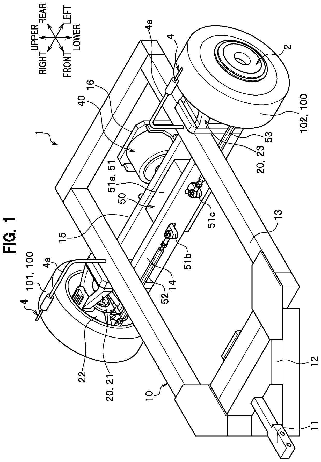
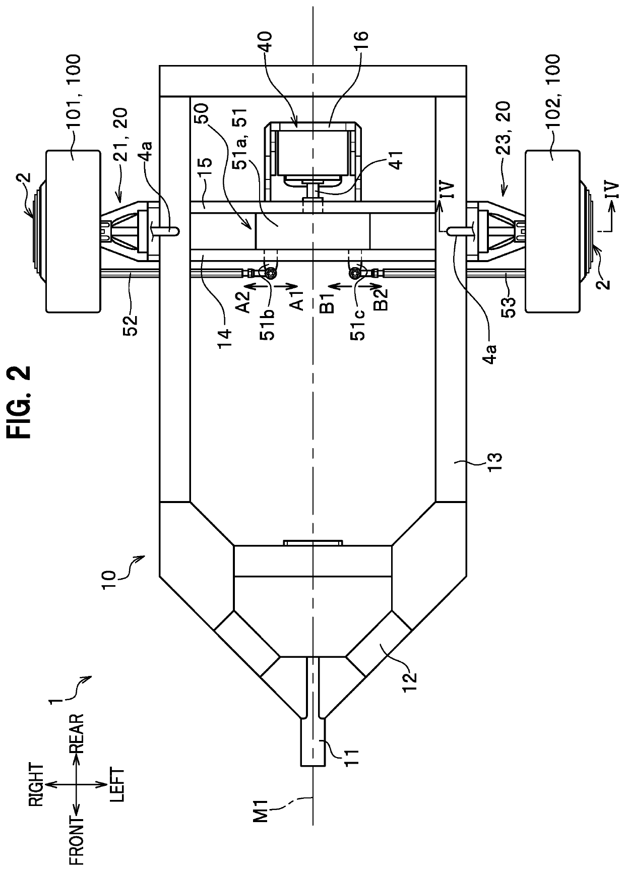
[0035]As seen in FIGS. 1 and 2, a tire tester 1 according to a first embodiment is attached to a towed member 10 towed by a movable member (not shown), and includes a plurality of tire holding units 20 each configured to detachably hold a tire 100 to rotate when the movable member travels, an actuator 40 for generating a driving force, and a transmission unit 50 for transmitting the driving force of the actuator 40 to the tire holding units 20.

[0036]It should be noted that the movable member may be a self-propelled two-wheel vehicle, a self-propelled three-wheel vehicle, and a self-propelled four-wheel vehicle, for instance.

[0037]Further, the tire tester 1 includes a load measuring unit 2 (see FIG. 4) for measuring a force (load) acting on a tire 100, a steering angle meter (toe angle meter; not shown) for measuring a steering angle (toe angle) of the tire 100, a temperature sensor 4 (see FIGS. 1 and 4) for measuring a surface temperature of the tire 100, a pitch sensor (not shown),...

second embodiment

[0103]As seen in FIG. 6, a tire tester 1A according to a second embodiment is attached to a towed member 10 towed by a movable member, and includes a plurality of tire holding units 20 (right tire holding unit 21 and left tire holding unit 23) configured to detachably hold tires 100, a plurality of actuators 40A attached to the towed member 10, and a plurality of transmission units 50A each configured to transmit the driving force of the actuator 40A to the tire holding unit 20.

[0104]Further, the tire tester 1A according to the second embodiment includes load measuring units 2 each interposed between a tire holding unit 20 (right tire holding unit 21 and left tire holding unit 23) and a tire 100 (right tire 101 and left tire 102).

[0105]Further, although not shown in the drawings, the tire tester 1A according to the second embodiment includes a steering angle meter (toe angle meter), a temperature sensor, a pitch sensor, and a turning lateral acceleration meter.

[0106]Therefore, the t...

third embodiment

[0125]As seen in FIG. 8, a tire tester 1B according to a third embodiment includes a plurality of tire holding units 20 attached to a four-wheel vehicle 200 as a self-propelled movable member, an actuator 40, and a transmission unit 50 for transmitting the driving force of the actuator 40 to the tire holding units 20.

[0126]The plurality of tire holding units 20 include a right tire holding unit 21 attached to the right side of the four-wheel vehicle (movable member) 200 with respect to a center line M2 of the four-wheel vehicle 200 and configured to hold the right tire 101, and a left tire holding unit 23 attached to the left side of the four-wheel vehicle (movable member) 200 with respect to the center line M2 and configured to hold the left tire 102.

[0127]The right tire holding unit 21 and the left tire holding unit 23 are arranged symmetrically with respect to the center line M2 of the four-wheel vehicle (movable member) 200.

[0128]The actuator 40 is disposed on the center line M2...


PUM


Abstract

A tire tester includes a plurality of tire holding units attached to a movable member or a towed member and each configured to detachably hold a tire, and one or more load measuring units for measuring a load acting on the tire. The plurality of tire holding units include a first tire holding unit configured to detachably hold a first tire, and one or more second tire holding units each configured to detachably hold a second tire. The second tire holding unit holds the second tire to generate a force opposite to a lateral component force generated by steering the first tire. The tire holding units are arranged such that at least one tire holding unit is disposed on each right and left side of the movable member or the towed member with respect to a center line passing through a lateral center thereof.

Description

CROSS-REFERENCE TO RELATED APPLICATIONS[0001]This application is a continuation application based on PCT / JP2018 / 013639, filed on Mar. 30, 2018, claiming priority based on Japanese Patent Application No. 2018-053544, filed in Japan on Mar. 20, 2018, the contents of which are incorporated herein by reference.TECHNICAL FIELD[0002]The present invention relates to a tire tester.RELATED ART[0003]Tire testers for determining tire characteristics measure a load applied to a tire while the tire is rotating.[0004]Therefore, a tire tester disclosed in the following Patent Literature Document 1 (JP 2013-156087A) and not providing a propulsive force is installed in a movable member such as a vehicle. The tire tester then measures a load applied to a tire when the tire is rotating during traveling of the movable member.[0005]An installation-type tire tester disclosed in the following Patent Literature Document 2 (JP 2011-137783A) causes a tire to rotate using a tire rotating device. The tire rota...

Claims


Application Information

Patent Timeline
Patent Type & Authority Patents(United States)
IPC IPC(8): G01M17/02
CPCG01M17/021G01M17/02G01M17/022
Inventor SHIBAHATA, YASUJINIIHARA, TATSURUISSHIKI, MIKISHIBAHATA, SHIGEHARUFUJIMOTO, HIROKAZU
Owner HITACHI ASTEMO LTD
Why Eureka
Try Eureka