Class of over-constrained two-rotation parallel mechanism with same kinematics
a parallel mechanism and kinematic technology, applied in the field of parallel mechanisms, can solve the problem that there are no related patents for over-constrained two-rotation parallel mechanisms with the same kinematics, and achieve the effects of large rotating range, high rigidity and precision, and large load-bearing capacity
- Summary
- Abstract
- Description
- Claims
- Application Information
AI Technical Summary
Benefits of technology
Problems solved by technology
Method used
Image
Examples
embodiment 1
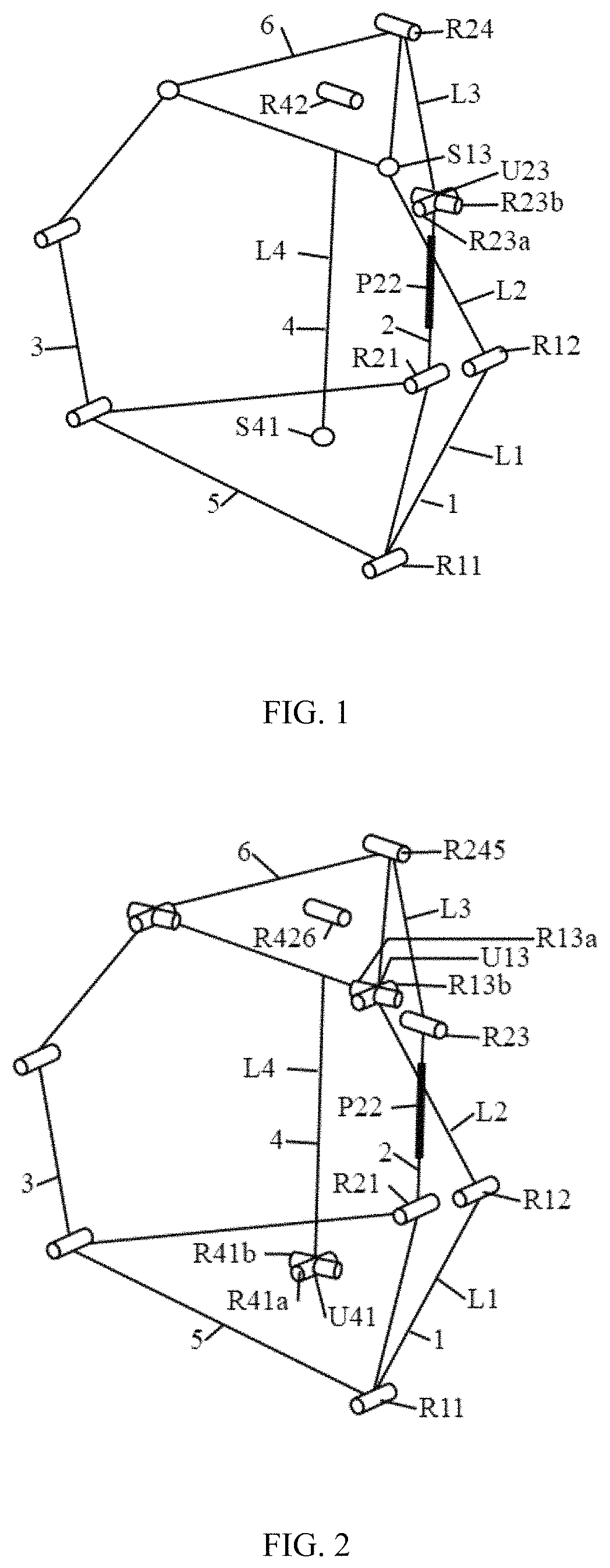
[0022]The present invention provides a class of over-constrained two-rotation parallel mechanism with same kinematics, as shown in FIG. 1, which includes a base 5, a moving platform 6 and four branches connecting the base and the moving platform, the base 5 and the moving platform 6 are both equilateral triangles, and the four branches connecting the base 5 and the moving platform 6 include a first branch 1, a second branch 2, a third branch 3, and a fourth branch 4. Both ends of each of the first branch 1, the second branch 2, and the third the branch 3 are respectively connected to the end points of the base 5 and the moving platform 6, both ends of the fourth branch 4 are respectively connected to the center points of the base 5 and the moving platform 6, the first branch 1 and the second branch 2 are driving branches, and the first rotating pair R11 in the first branch 1 and the first moving pair P22 in the second branch 2 are both driving pairs.
[0023]The first branch 1 and the ...
embodiment 2
[0026]The technical solution adopted in the second aspect of the present invention, as shown in FIG. 2, includes a base 5, a moving platform 6, and four branches connecting the base and the moving platform. The base 5 and the moving platform 6 are both equilateral triangles, and the four branches connecting the base 5 and the moving platform 6 include a first branch 1, a second branch 2, a third branch 3, and a fourth branch 4. Both ends of each of the first branch 1, the second branch 2, and the third branch 3 are respectively connected to the end points of the base 5 and the moving platform 6, both ends of the fourth branch 4 are respectively connected to the center points of the base 5 and the moving platform 6. The first branch 1 and the second branch 2 are driving branches, and the first rotating pair R11 in the first branch 1 and the first moving pair P22 in the second branch 2 are both driving pairs.
[0027]The first branch 1 and the third branch 3 alternatively consist of a fi...
embodiment 3
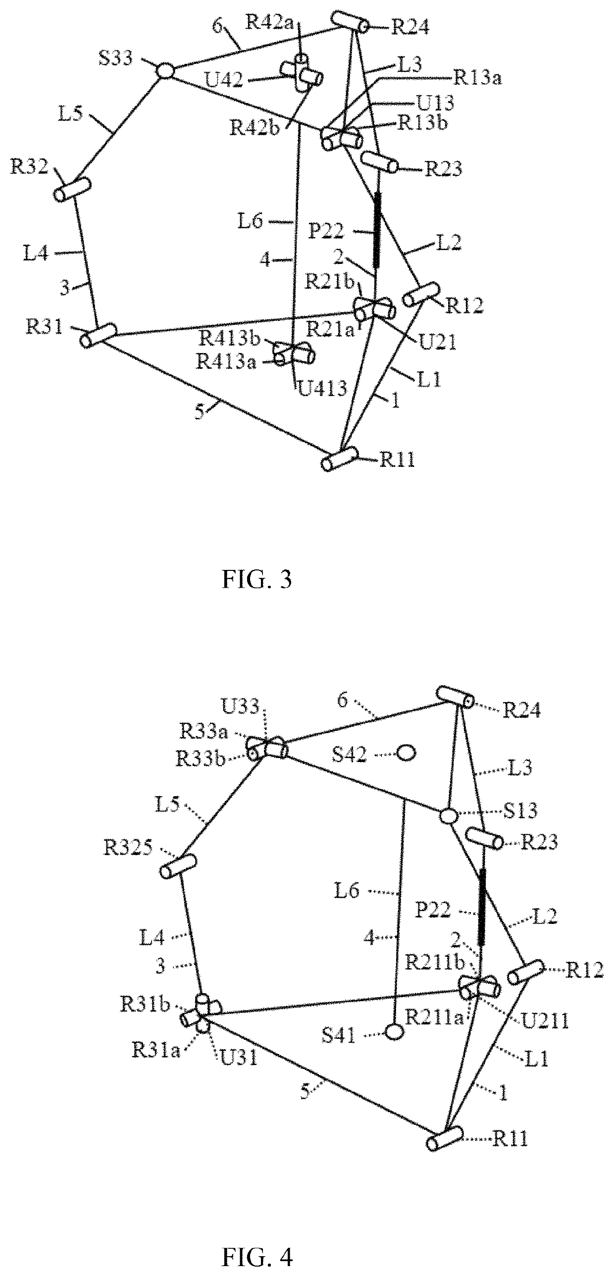
[0030]The technical solution adopted in the third aspect of the present invention, as shown in FIG. 3, includes a base 5, a moving platform 6, and four branches connecting the base and the moving platform. The base 5 and the moving platform 6 are both equilateral triangles, and the four branches connecting the base 5 and the moving platform 6 include a first branch 1, a second branch 2, a third branch 3, and a fourth branch 4. Both ends of each of the first branch 1, the second branch 2, and the third branch 3 are respectively connected to the end points of the base 5 and the moving platform 6, both ends of the fourth branch 4 are respectively connected to the center points of the base 5 and the moving platform 6. The first branch 1 and the second branch 2 are driving branches, and the first rotating pair R11 in the first branch 1 and the first moving pair P22 in the second branch 2 are both driving pairs.
[0031]The first branch 1 alternatively consists of a first rotating pair R11, ...
PUM
 Abstract
Description
Claims
Application Information
 - R&D
- Intellectual Property
- Life Sciences
- Materials
- Tech Scout
- Unparalleled Data Quality
- Higher Quality Content
- 60% Fewer Hallucinations
Browse by: Latest US Patents, China's latest patents, Technical Efficacy Thesaurus, Application Domain, Technology Topic, Popular Technical Reports.
© 2025 PatSnap. All rights reserved.Legal|Privacy policy|Modern Slavery Act Transparency Statement|Sitemap|About US| Contact US: help@patsnap.com


