Vehicle air conditioning circuit using a refrigerant fluid in the supercritical state

a technology of refrigerant fluid and vehicle air conditioning, which is applied in the direction of lighting and heating apparatus, heating types, applications, etc., can solve the problems of affecting the comfort of the occupants of the vehicle, unable to draw heat, and considerable delay, and achieve the effect of increasing the speed of heating

Inactive Publication Date: 2001-06-14
VALEO SYST THERMIQUES
View PDF0 Cites 41 Cited by
  • Summary
  • Abstract
  • Description
  • Claims
  • Application Information

AI Technical Summary

Benefits of technology

0005] An object of the present invention is to enable a space, for example the cabin of a vehicle, to be heated more rapidly than hitherto when the engi...

Problems solved by technology

When the engine is cold, no heat can be drawn from it for the purpose of heating the cabin.
This results in a considerable delay before the cabin can be brought to the required temperature, and is consequently detrimental to the comfort of the occupan...

Method used


Image

  • Vehicle air conditioning circuit using a refrigerant fluid in the supercritical state
  • Vehicle air conditioning circuit using a refrigerant fluid in the supercritical state
  • Vehicle air conditioning circuit using a refrigerant fluid in the supercritical state

Examples


Embodiment Construction

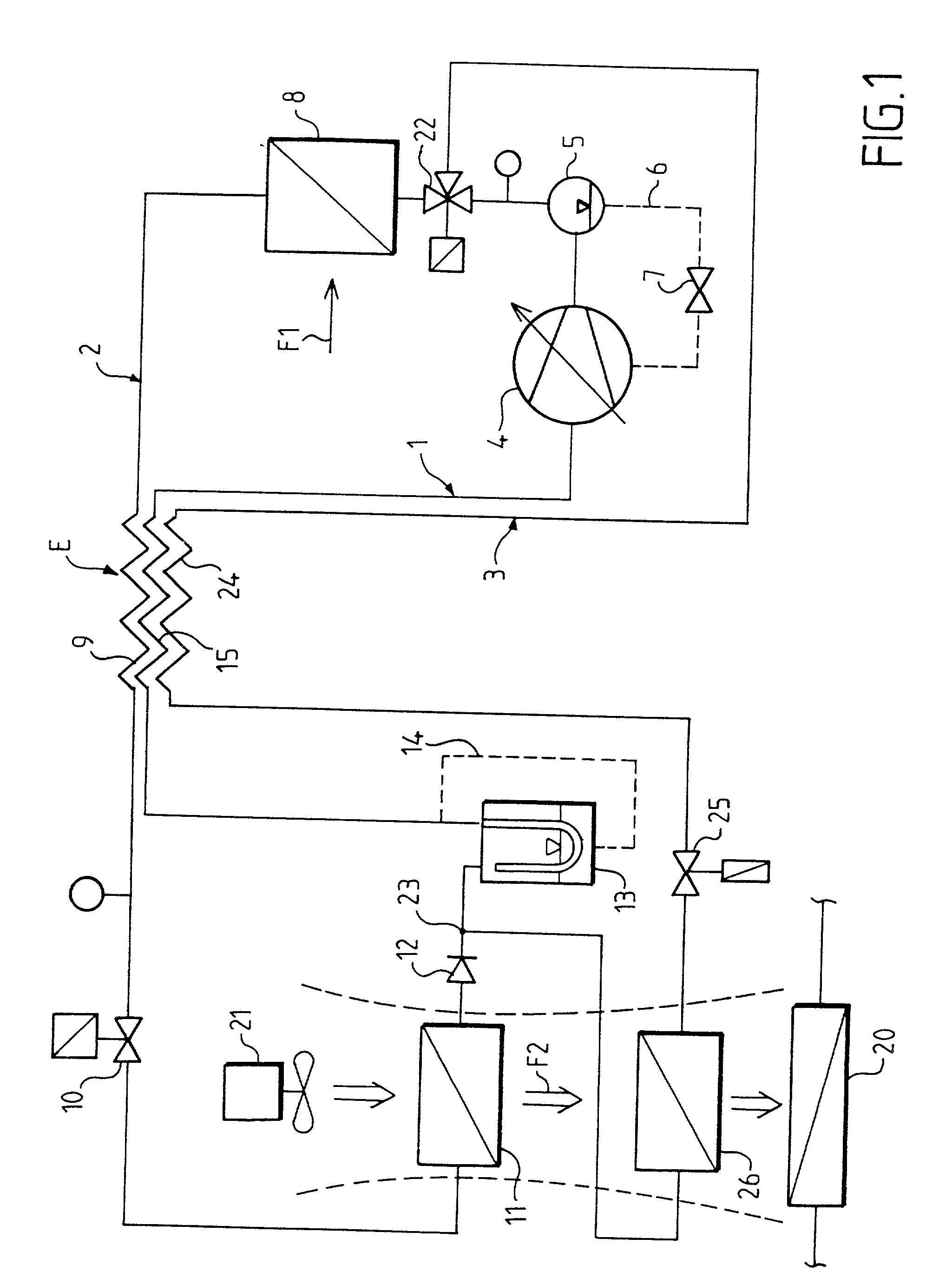
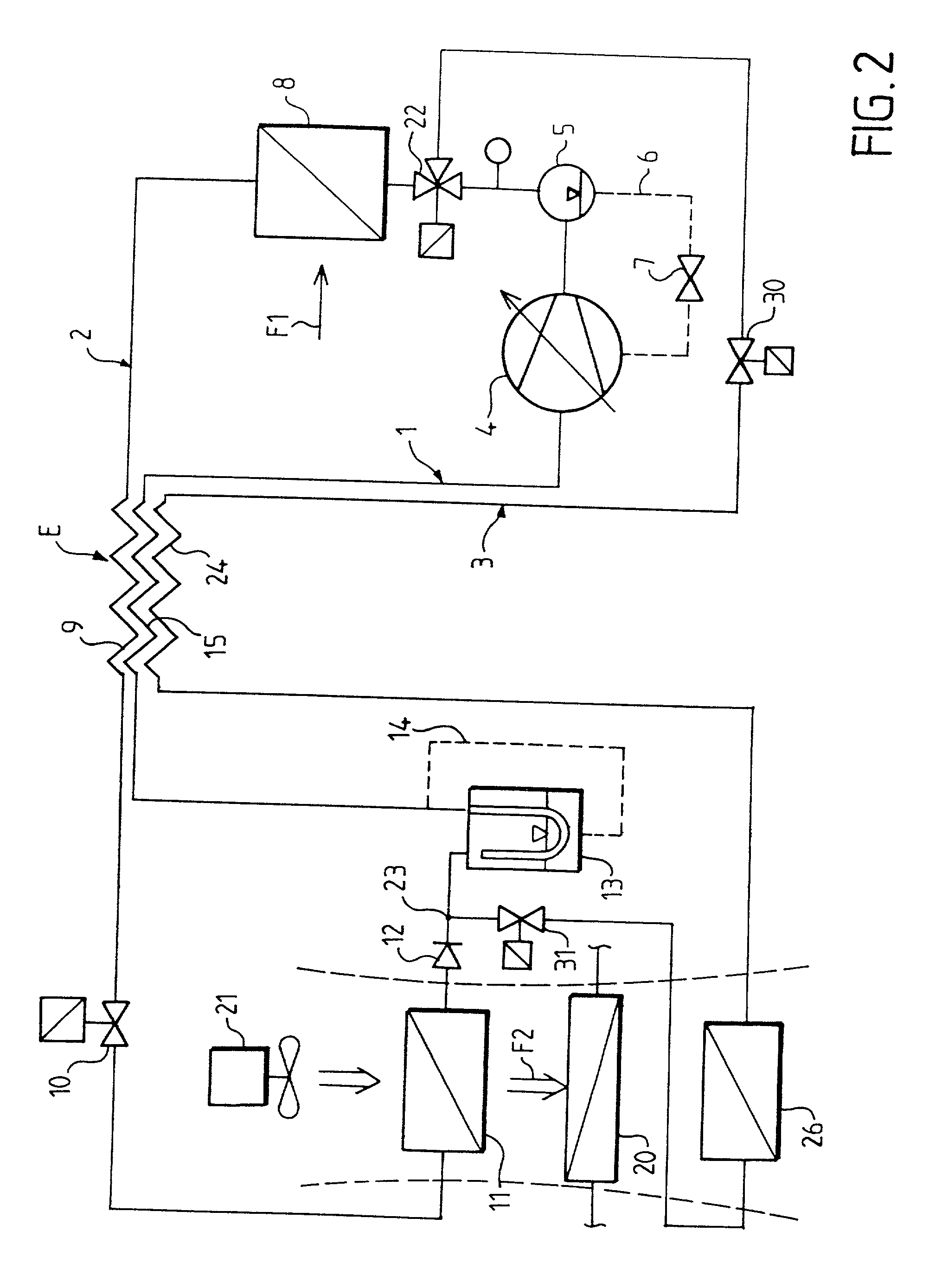
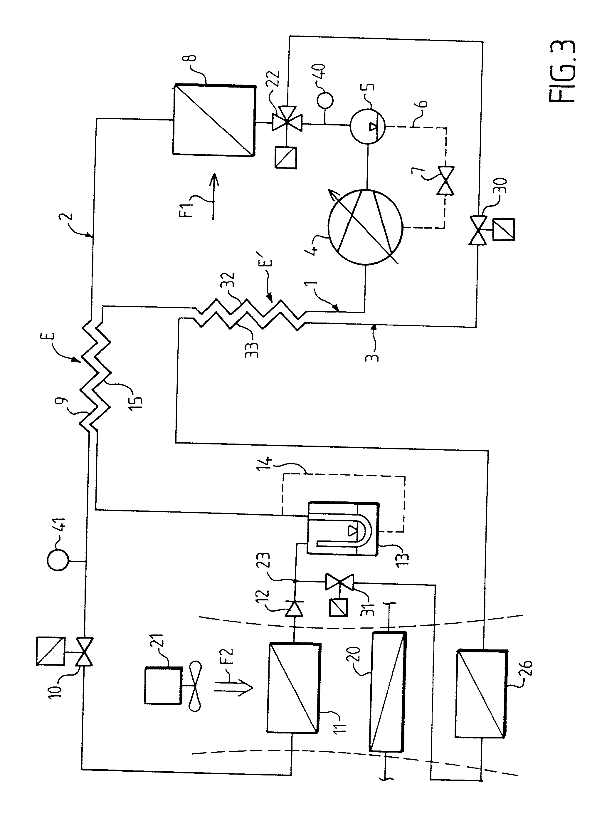
[0024] In the present description, the expression "air conditioning apparatus" means an apparatus which enables the temperature in a space (such as the cabin of a vehicle) to be regulated, either by removing heat from that space or by putting heat into the space, according to the requirements of the user. Each of the embodiments of the apparatus shown in the drawings comprises a refrigerant fluid circuit which has three branches 1, 2 and 3. The branches 1 and 2 constitute a so-called air conditioning loop which is used to extract heat from the cabin; the branches 1 and 3 together constitute a heating loop whereby heat is supplied to the cabin. This circuit is arranged to enable the pressure of a refrigerant fluid, and especially carbon dioxide, to vary on either side of the critical pressure.

[0025] A brief description will first be given of the air conditioning loop, which is practically identical in the four versions shown in the drawings, and which is known per se. This loop compr...


PUM


Abstract

Refrigerant fluid such as CO2, compressed to the supercritical pressure by a compressor, is delivered selectively through a three-way valve, either into a branch of the circuit containing a cooler, an expansion device and an evaporator for cooling the cabin of a vehicle, or into a branch containing another expansion device and a heat exchanger for the purpose of heating the cabin.

Description

[0001] This invention relates to air conditioning apparatus. In particular, the invention is directed to air conditioning apparatus, especially for the cabin of a vehicle, in which the apparatus includes: a first circuit branch for the flow of a refrigerant fluid therein, the first circuit branch containing a compressor which is arranged to receive the refrigerant fluid in the gaseous state and to compress it to a supercritical pressure, and a second circuit branch containing a first heat exchanger which is adapted to cool the fluid compressed by the compressor at a substantially constant pressure, by transferring heat from a first external medium to the fluid; a first expansion device which is adapted to reduce the pressure in the fluid leaving the first heat exchanger, so as to put at least some of the fluid in the liquid state; and an evaporator which is arranged to change the state of the fluid received from the first expansion device from the gaseous to the liquid state at a su...

Claims


Application Information

Patent Timeline
IPC IPC(8): B60H1/00F24F3/153F25B9/00F25B40/00F25B41/04
CPCB60H1/00921B60H2001/00942B60H2001/00957F24F3/153F25B9/008F25B40/00F25B41/04F25B2309/061F25B2600/0253F25B2600/2501Y10S62/17F25B41/20
Inventor KARL, STEFAN
Owner VALEO SYST THERMIQUES
Why Eureka
Try Eureka