

Vehicle ceiling-mounting electric equipment assembly
a technology for electric equipment and ceiling mounts, which is applied in the direction of roofs, lighting and heating apparatuses, printed circuit non-printed electric components associations, etc., can solve the problems of increasing the time and labor, and increasing the number of components
- Summary
- Abstract
- Description
- Claims
- Application Information
AI Technical Summary
Problems solved by technology
Method used
Image

Examples
Embodiment Construction
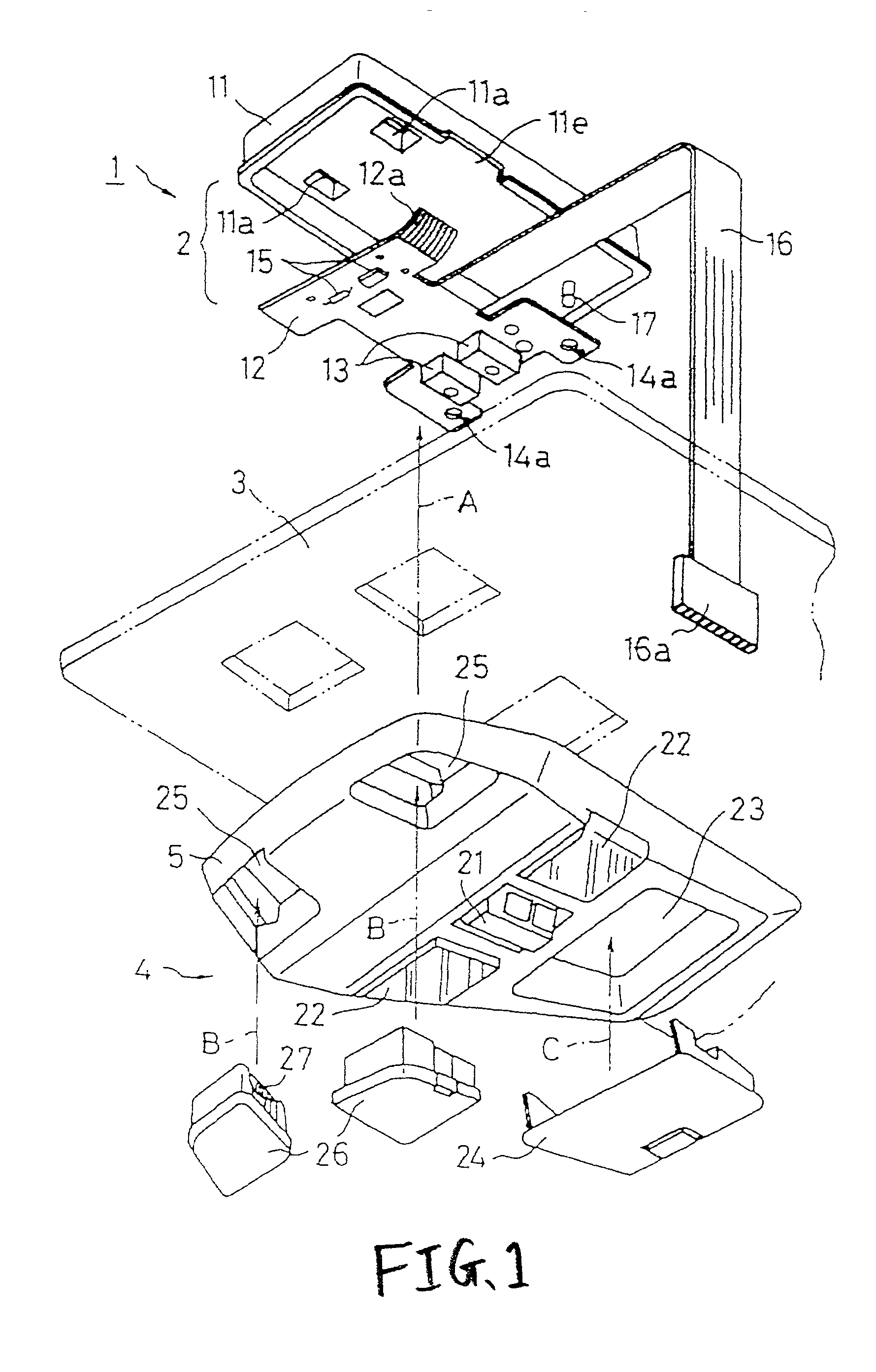
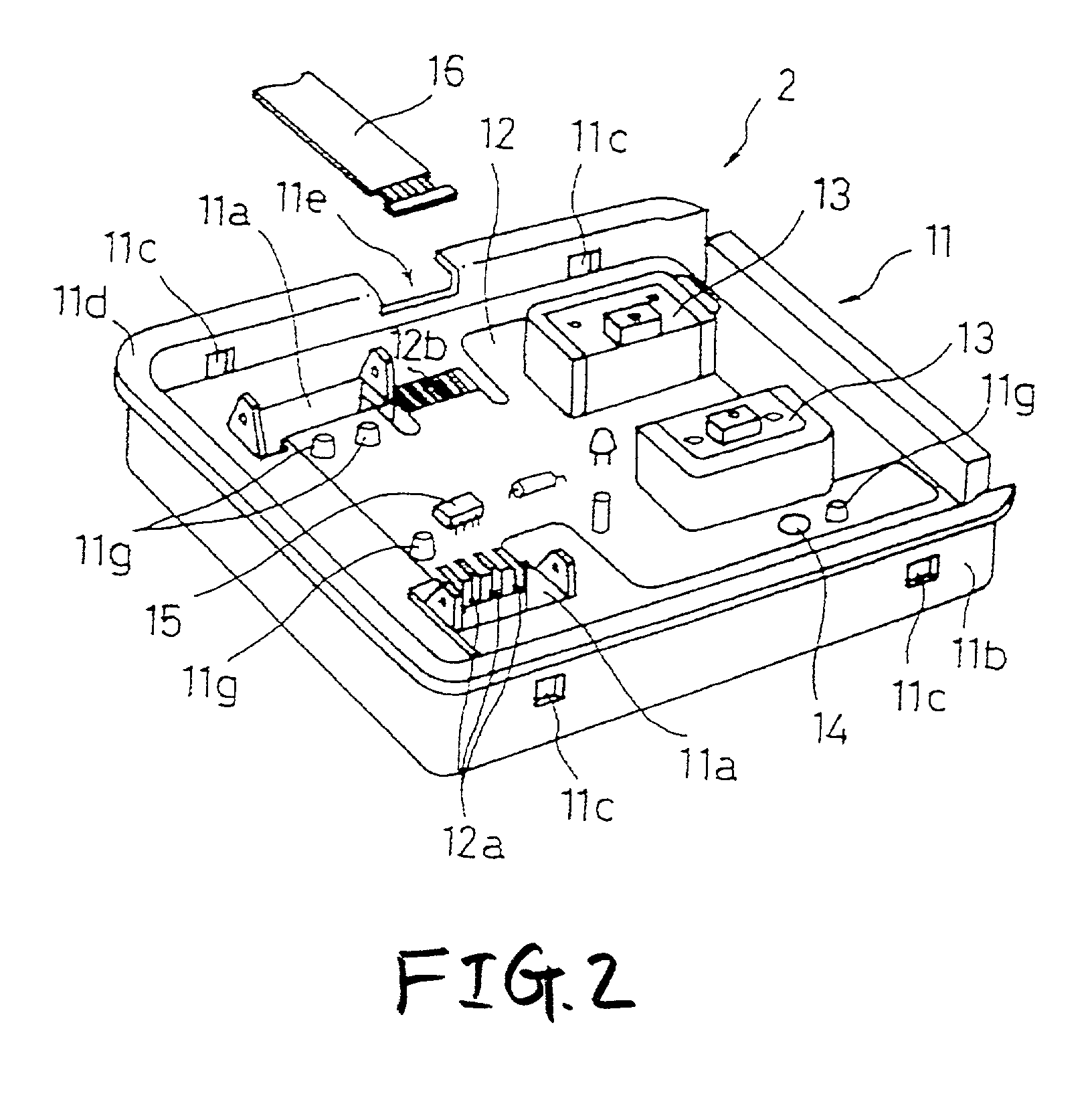
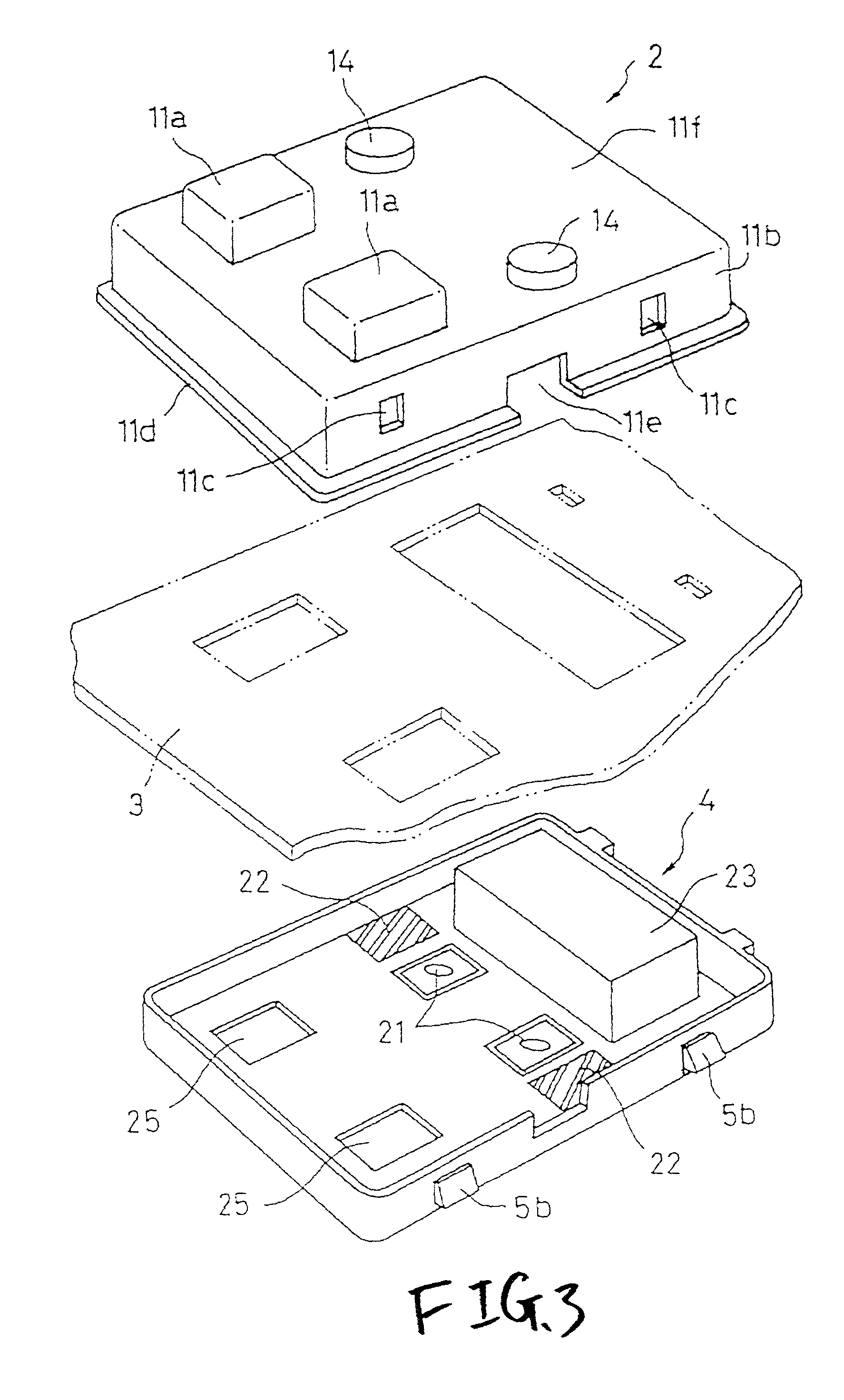
[0039] One preferred embodiment of a vehicle ceiling-mounting electric equipment assembly of the invention will now be described in detail with reference to FIGS. 1 to 6. FIG. 1 is an exploded, perspective view showing the construction of the vehicle ceiling-mounting electric equipment assembly. FIG. 2 is a perspective view showing an internal structure of a lamp unit. FIG. 3 is an exploded, perspective view showing the mounting of the lamp unit and an overhead console relative to each other. FIG. 4 is a perspectives view of an important portion, showing a retaining structure of a flexible printed circuit. FIG. 5 is a perspective view of an important portion, showing the construction of a lamp socket portion. FIG. 6 is a cross-sectional view showing the construction of the vehicle ceiling-mounting electric equipment assembly.
[0040] In the description of the embodiment, the overall construction will be first described with reference to FIG. 1, and then the constructions and operation...
PUM
 Abstract
Description
Claims
Application Information