Lubricating structure for output shaft bearing portion in transmission

a technology for transmission shafts and lubricating structures, which is applied in the direction of drip or splash lubrication, machine/engines, and lubrication of shafts, etc., can solve the problems of difficulty in securing the strength of output shafts

Inactive Publication Date: 2001-08-09
HONDA MOTOR CO LTD
View PDF0 Cites 40 Cited by
  • Summary
  • Abstract
  • Description
  • Claims
  • Application Information

AI Technical Summary

Problems solved by technology

This results in a difficulty in securing a strength of the output shaft.

Method used


Image

  • Lubricating structure for output shaft bearing portion in transmission
  • Lubricating structure for output shaft bearing portion in transmission
  • Lubricating structure for output shaft bearing portion in transmission

Examples


Embodiment Construction

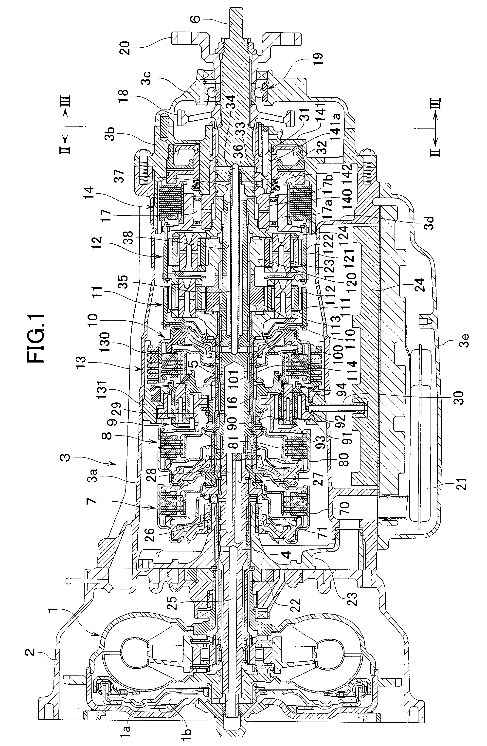
[0015] FIG. 1 shows an automatic transmission for a motor vehicle. This transmission is provided with a transmission casing 3 which is coupled to a torque converter casing 2 containing therein a fluid torque converter 1 equipped with a lock-up clutch 1a. Inside this transmission casing 3, there are rotatably supported on the same axial line an input shaft 4 which is coupled to the fluid torque converter 1, an intermediate shaft 5, and an output shaft 6. Around these shafts 4, 5, 6, there are disposed in the order mentioned, as seen from the side of the torque converter casing 2, a first hydraulic clutch 7, a second hydraulic clutch 8, a first planetary gear mechanism 9, a third hydraulic clutch 10, a second planetary gear mechanism 11, and a third planetary gear mechanism 12. Further, there is disposed a first hydraulic brake 13 around the third hydraulic clutch 10, and a second hydraulic brake 14 is disposed at an axial front of the third planetary gear mechanism1 12.

[0016] Each of...


PUM


Abstract

An output shaft bearing portion which is provided in an extension housing to be attached to an outside of an end wall portion of a casing main body of a transmission casing is lubricated by lubrication oil which is supplied to lubricating portions inside the casing main body. In the end wall portion there is formed an oil guide passage which guides the lubrication oil supplied to the lubricating portions inside the casing main body. Inside the extension housing, there is formed a rib which guides the lubrication oil flown from the oil guide passage, into a position in which the lubrication oil can be scraped by a gear wheel provided inside the extension housing. The lubrication oil scraped by the gear wheel is supplied to the output shaft bearing portion.

Description

[0001] 1. Field of the Invention[0002] The present invention relates to a lubricating structure for an output shaft bearing portion (i.e., a bearing portion of an output shaft) in a transmission such as an automatic transmission of a motor vehicle.[0003] 2. Description of Related Art[0004] Conventionally, as a transmission for a motor vehicle, there has hitherto been known the following one. Namely, the transmission is made up of an extension housing which is attached to an axial outside of an end wall portion of a casing main body of a transmission casing. This extension housing is provided with an output shaft bearing portion for rotatably supporting an output shaft which protrudes or projects through the end wall portion. Inside the extension housing there is contained a gear wheel such as a parking gear wheel or a vehicle speed detection gear wheel which is coupled to the output shaft.[0005] In this kind of transmission, however, lubrication oil is supplied to the output shaft b...

Claims


Application Information

Patent Timeline
Patent Type & Authority Applications(United States)
IPC IPC(8): F16H3/66F16H57/03F16H57/04
CPCF16H3/66F16H57/02F16H57/0423F16H57/0471F16H2057/02013F16H2057/02047F16H2200/0052F16H2200/201Y10T74/2186
Inventor KAGEYAMA, ISAMUIMAMURA, MASAHIROOGAWA, GAKU
Owner HONDA MOTOR CO LTD
Why Eureka
Try Eureka