Cooling device for liquid-cooled type internal combustion engine

a technology of internal combustion engine and cooling device, which is applied in the direction of engine cooling apparatus, measurement device, machine/engine, etc., can solve the problems of power consumption, problem of conventional cooling device,

Inactive Publication Date: 2001-09-13
DENSO CORP
View PDF0 Cites 38 Cited by
  • Summary
  • Abstract
  • Description
  • Claims
  • Application Information

AI Technical Summary

Problems solved by technology

The conventional cooling device, however, is problematic from a point of

Method used


Image

  • Cooling device for liquid-cooled type internal combustion engine
  • Cooling device for liquid-cooled type internal combustion engine
  • Cooling device for liquid-cooled type internal combustion engine

Examples


first embodiment

[0022] (First Embodiment)

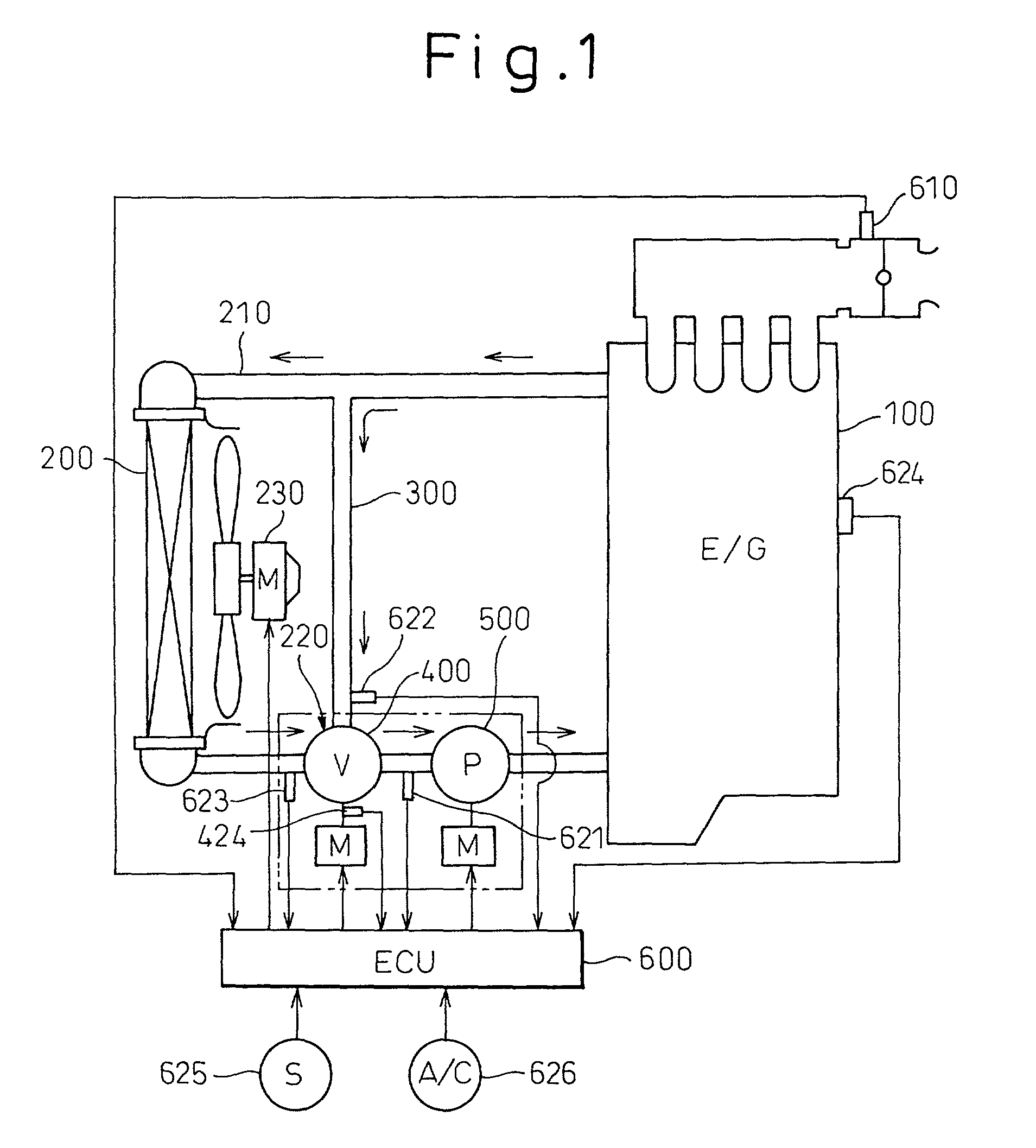
[0023] In this embodiment, a cooling device for a liquid-cooled type internal combustion engine according to the present invention is applied to a water-cooled type engine (a liquid-cooled type internal combustion engine) for a vehicle. FIG. 1 illustrates a schematic view of the cooling device of this embodiment.

[0024] In FIG. 1, reference numeral 200 denotes a radiator for cooling water (coolant) circulating the interior of a water-cooled type engine (hereinafter referred to as an engine) 199, and 210 denotes a radiator circuit for circulating the coolant through the radiator 200.

[0025] Reference numeral 300 denotes a bypass circuit for guiding the coolant flowing out of the engine 100 to a region of the radiator circuit 210 on an exit side of the radiator 200, while making the coolant bypass the radiator 200. At a position 220 at which the coolant from the bypass circuit 300 and that from the radiator circuit 210 meet, a rotary type electric flow rate cont...

second embodiment

[0060] (Second Embodiment)

[0061] According to the first embodiment, the power consumption of the pump 500 can be saved even if the same discharge flow rate is obtained, by increasing the valve opening degree .theta. to reduce the water flow resistance and thus lower the pump duty. It has, however, been found from the more detailed study that there is the following problem.

[0062] That is, FIG. 9 is an equivalent circuit showing a water flow resistance of a water flow system in the cooling device shown in FIG. 1. In some cases, a total water flow resistance may become minimum when the valve opening degree .theta. is smaller than 100% if the water flow resistances are so distributed in the respective parts. The valve opening degree .theta. at which the total water flow resistance becomes minimum is hereinafter referred to as a minimum resistance opening degree .theta.x.

[0063] If the valve opening degree .theta. becomes the minimum resistance opening degree .theta.min, for example, when...


PUM


Abstract

In a cooling device for an engine, having a motor-driven pump and a flow rate control valve, to obtain a predetermined discharge flow rate (circulating coolant amount) from the pump 500, a pump duty is minimized while maintaining a water flow resistance as low as possible (maintaining a valve opening degree theta as large as possible). Thereby, a value of an electric current flowing through the pump 500 becomes smaller to decrease the energy consumption (power consumption).

Description

[0001] 1. Field of the Invention[0002] The present invention relates to a cooling device for a liquid-cooled type internal combustion engine, which is suitably applicable to a vehicle.[0003] 2. Description of the Related Art[0004] In a conventional cooling device for a liquid-cooled type internal combustion engine, an electric (motor-driven) pump for circulating cooling water and an electric flow rate control valve for regulating a flow rate of cooling water circulating in a radiator are controlled independently from each other.[0005] The conventional cooling device, however, is problematic from a point of view of decreasing the power (electric energy) consumption of the pump.[0006] An object of the present invention is to decrease, in a cooling device for a liquid-cooled type internal combustion engine including an electric (motor-driven) pump and an electric flow rate control valve, the power (electric energy) consumption of the pump.[0007] To achieve the above object, according t...

Claims


Application Information

Patent Timeline
IPC IPC(8): F01P7/04F01P7/14F01P7/16
CPCF01P7/048F01P7/164F01P7/167F01P2007/146F01P2025/30F01P2025/36F01P2025/62
Inventor SUZUKI, KAZUTAKATAKAHASHI, EIZO
Owner DENSO CORP
Why Eureka
Try Eureka