Non-aqueous electrolytic solution secondary battery

a secondary battery, non-aqueous electrolytic technology, applied in secondary cell servicing/maintenance, cell components, sustainable manufacturing/processing, etc., can solve the problems of deterioration of power and cycle life characteristics, short charging/discharging cycle life characteristic of lithium-ion secondary battery,

Inactive Publication Date: 2001-10-18
SHIN KOBE ELECTRIC MASCH CO LTD
View PDF0 Cites 40 Cited by
  • Summary
  • Abstract
  • Description
  • Claims
  • Application Information

AI Technical Summary

Problems solved by technology

Conventionally, in a lithium secondary battery using a metallic lithium or a lithium alloy for a negative electrode, there has been a drawback in that internal shorts between a positive electrode and the negative electrode occur since a dendritic lithium deposits on the negative electrode at the time of charging.
When the complex oxide expressed by a chemical formula Li.sub.xMn.sub.yO.sub.2 (0.4.ltoreq.x.ltoreq.1.35, 0.65.ltoreq.y.ltoreq.1.0) is used as the positive electrode active material, there were drawbacks in that a charging / discharging cycle life characteristic of the lithium-ion secondary battery becomes short and a power (output) characteristic thereof becomes lowered.
Particularly, when the battery is used at a high temperature of 50.degree. C. or more, there are disadvantages in that the power and cycle life characteristics deteriorate since the manganese elutes from the positive electrode and the eluted manganese forms a nonconductive (inert) coating on the surface of the negative electrode.
A high output can be gained when the discharging is carried out at a small current in the conventional lithium-ion secondary battery, however, it had a drawback in that the output goes down remarkably when the discharging is carried out at a large current.
This brings about an increase in an internal resistance and results in a drop in the output.

Method used


Image

  • Non-aqueous electrolytic solution secondary battery
  • Non-aqueous electrolytic solution secondary battery

Examples


examples a-1

, A-2, Control A-1

[0028] As shown in the following Table 1, in Example A-1, Example A-2 and Control A-1, the positive porosity was set to 30%, and the negative porosity was set to 30%. The separator porosity was set to 40% in Example A-1, 30% in Example A-2, and 25% in Control A-1, respectively.

1 TABLE 1 POSITIVE NEGATIVE SEPARATOR POROSITY POROSITY POROSITY (%) (%) (%) Example A-1 30 30 40 Example A-2 30 30 30 Control A-1 30 30 25 Example A-3 40 40 60 Example A-4 40 40 50 Example A-5 40 40 40 Control A-2 40 40 30 Example A-6 20 20 30 Example A-7 20 20 20 Control A-3 20 20 15 Example A-8 50 50 60 Example A-9 50 50 50 Control A-4 50 50 40

examples a-3

to A-5, Control A-2

[0029] As shown in Table 1, in Example A-3 to Example A-5 and Control A-2, the positive porosity was set to 40%, and the negative porosity was set to 40%. The separator porosity was set to 60% in Example A-3, 50% in Example A-4, 40% in Example A-5, and 30% in Control A-2, respectively.

examples a-6

, A-7, Control A-3

[0030] As shown in Table 1, in Example A-6, Example A-7 and Control A-3, the positive porosity was set to 20%, and the negative porosity was set to 20%. The separator porosity was set to 30% in Example A-6, 20% in Example A-7, and 15% in Control A-3, respectively.


PUM

PropertyMeasurementUnit
porosityaaaaaaaaaa
porosityaaaaaaaaaa
porosityaaaaaaaaaa

Abstract

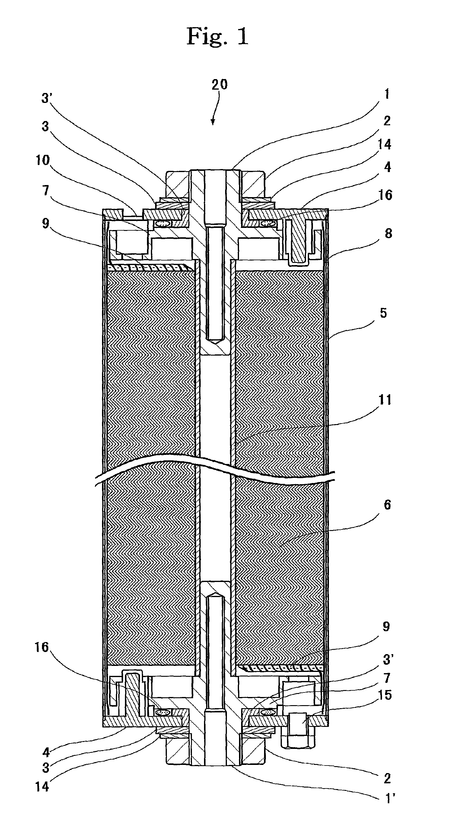
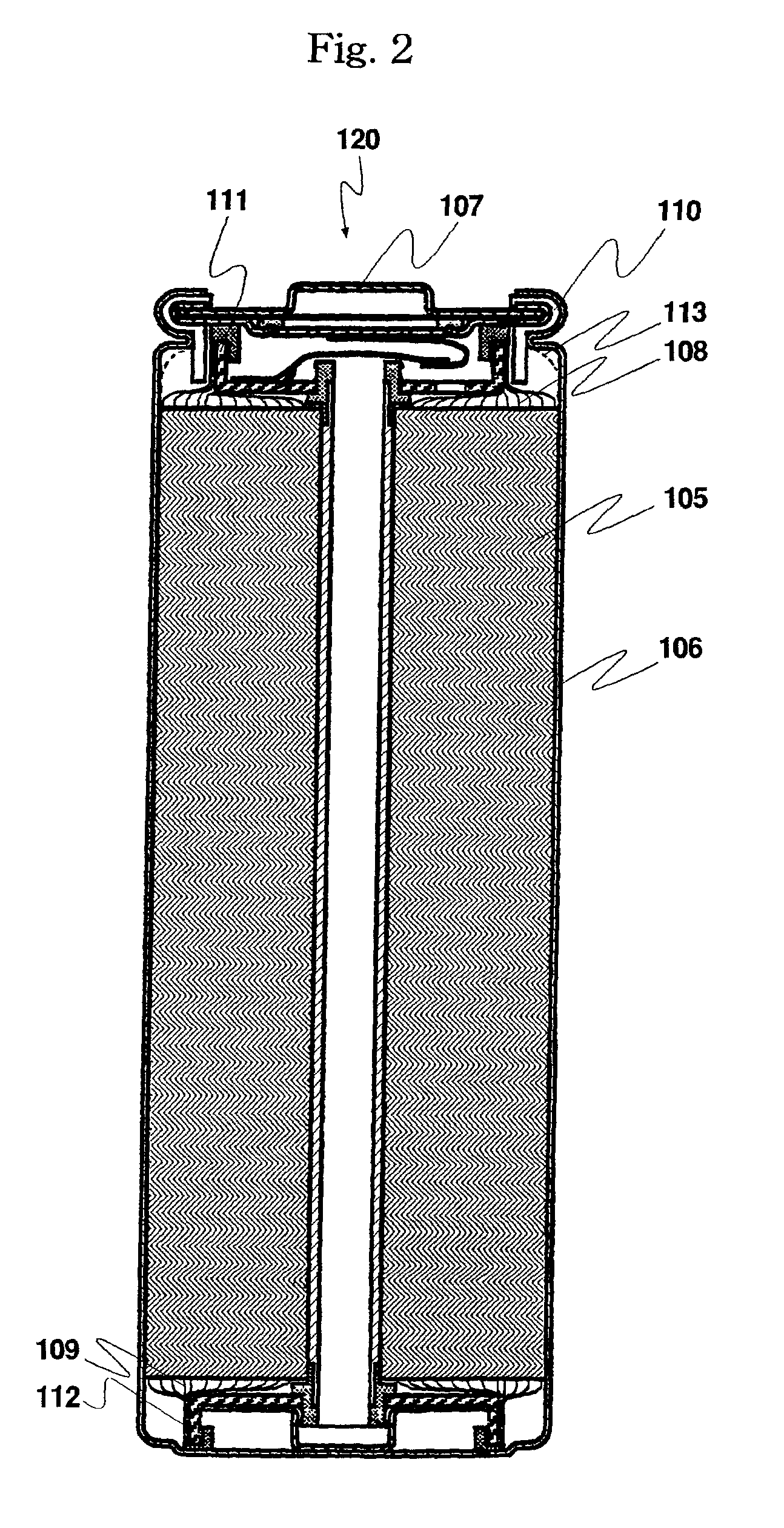
A non-aqueous electrolytic secondary battery that can prevent a drop in the power even in a large current discharge is provided. Porosity of a separator is larger than or the same as porosity of a positive electrode mixture and a porosity of a negative electrode mixture. Particularly, the porosity of the positive electrode mixture is 20% to 50%, the porosity of the negative electrode mixture is 20% to 50%, and the porosity of the separator is 20% to 60%. The separator becomes rich in the volume of the electrolytic solution that infiltrates into interfacial aperture between the separator and the negative electrode. When the large current discharge is carried out in a short time, lithium-ions are released / occluded from the electrodes and the electrolytic solution can gain the released / occluded lithium-ions with a small interfacial resistance.

Description

[0001] This patent application is based on a Japanese patent application, Ser. number 2000-30095, entitled "Lithium-Ion Secondary Battery", of Iguchi et al., filed on Feb. 8, 2000, a Japanese patent application, Ser. number 2000-31295, entitled "Non-aqueous Electrolytic Solution Secondary Battery", of Takatsuka et al., filed on Feb. 9, 2000, Japanese patent applications, Ser. numbers 2000-147395 and 2000-147532, both entitled "Lithium-Ion Battery", of Nakai et al., filed on May 19, 2000, and a Japanese patent application, Ser. number 2000-195428, entitled "Non-Aqueous Electrolytic Solution Lithium Secondary Battery", of Iguchi et al., filed on Jun. 29, 2000.[0002] The present application relates to a non-aqueous electrolytic solution secondary battery, and in particular relates to a non-aqueous electrolytic solution secondary battery where a winding group, where a positive electrode having a positive electrode collector applied with a positive electrode mixture including a positive ...

Claims


Application Information

Patent Timeline
Patent Type & Authority Applications(United States)
IPC IPC(8): H01M4/50H01M4/505H01M6/10H01M10/0525H01M10/36H01M10/42H01M50/179H01M50/417H01M50/451H01M50/489H01M50/491H01M50/548H01M50/559H01M50/566H01M50/567
CPCH01M2/06H01M2/1653H01M2/1686H01M2/30H01M4/505H01M6/10H01M10/0525H01M2010/4292Y02E60/122Y02T10/7011Y02E60/10Y02P70/50H01M50/417H01M50/179H01M50/489H01M50/491H01M50/559H01M50/451H01M50/548H01M50/566H01M50/567Y02T10/70
Inventor HIRONAKA, KENSUKENAKAI, KENJIKOISHIKAWA, YOSHIMASATAKATSUKA, YUICHIHARA, KENJIIGUCHI, TOMOHIROSUZUKI, KATSUNORIHIGASHIMOTO, KOJINAKANO, TAKESHI
Owner SHIN KOBE ELECTRIC MASCH CO LTD
Why Eureka
Try Eureka