
Signal processing circuit free from erroneous data and the information storage apparatus including the signal processing circuit

a signal processing circuit and data processing technology, applied in the field of signal processing circuits free from erroneous data and information storage apparatus including signal processing circuits, can solve problems such as and affecting the accuracy of recording information

Inactive Publication Date: 2001-10-25
HITACHI LTD
View PDF0 Cites 7 Cited by
  • Summary
  • Abstract
  • Description
  • Claims
  • Application Information

AI Technical Summary

Problems solved by technology

But, if an abnormal condition occurs, for example, a significant shock or the like is applied to the apparatus, a write head is heavily displaced from a predetermined track.
And, it was found that the recorded information might be misread under the aforesaid abnormal condition.
The write head position at the previous recording and the write head position at the new information recording do not agree completely because of an error of positioning accuracy level.
The unerased area degrades an error rate especially at the off track position.
Such a large unerased area has a possibility that the previously recorded data themselves are erroneously read.
That leads to erroneous data in addition to the simple degradation of the error rate seen in FIGS. 7(a)-7(c).
Misread under the situation of (2) above tends to cause erroneous data because ECC (Error Correction Code) does not operate effectively, and if ECC is reinforced, even a small volume of previously recorded data is read.
When the write inhibit slice as indicated by (1) above is determined small, write ready is not established until sufficient positioning accuracy is determined, resulting in degradation of effective data throughput of the apparatus.
And, when the read track width is designed large as indicated by (2) above, it becomes easy to cause adjacent crosstalk and to read the previously recorded data, and an error rate is degraded.
And, an uncorrectable error might be caused in some cases.

Method used


Image

  • Signal processing circuit free from erroneous data and the information storage apparatus including the signal processing circuit
  • Signal processing circuit free from erroneous data and the information storage apparatus including the signal processing circuit
  • Signal processing circuit free from erroneous data and the information storage apparatus including the signal processing circuit

Examples


embodiment 1

[0051] Embodiment 1

[0052] FIG. 10 shows a flow chart of a write operation according to the first embodiment of the invention. A rotary actuator is operated upon receiving a write command from a controller, and a magnetic head is caused to seek a target track. According to a position signal demodulated from a servo signal, the target position and the head's present position are compared so to position the head at the target position. When the magnetic head reaches the target position, it is determined as a state of write operation ready.

[0053] Meanwhile, a write frequency from the controller to the data sector, namely the number of overwriting in the same sector, is monitored by a counter, and a coding form is determined depending on the number counted by the counter. The counted number and data sector position information are recorded on a second memory at every write operation. As position information of the data sector, CHS is used in the embodiment. Three different coding forms a...

embodiment 2

[0059] Embodiment 2

[0060] FIG. 14 shows a flow chart of a write operation according to the second embodiment of the invention. A write command is received from the controller, and the rotary actuator is operated to make the magnet head seek a target track. According to the position signal demodulated from a servo signal, the target position and the head's present position are compared to position the head at the target position. When the magnetic head reaches the target position, it is determined as a state of write operation ready.

[0061] Meanwhile, a frequency of overwriting in the data sector from the controller is monitored by the counter, and a scrambler initial value is determined from the number indicated by the counter. To change the scrambler initial value, a plurality of scrambler initial values are previously kept in a register within the signal processing circuit, and the respective scrambler initial values are allotted according to the overwriting frequencies counted by ...


PUM


Abstract

A magnetic storage apparatus is provided with unit for identifying the frequency of overwriting storage at the time of overwriting in the same data sector, and depending on the frequency of overwriting, a code for coding or a scrambler initial value is changed at every overwrite operation. The modulation code has the same code rate so that a data length does not change at every write operation. A number corresponding to the present modulation code of each data sector is stored on a memory, and the aforesaid number is also written as an additional bit in the data sector on a medium. Data are read only when the modulation coding number on the memory and the modulation coding number on the medium, which are compared, agree with each other. If they do not agree, offset reading is performed until they agree, and then the read operation is performed.

Description

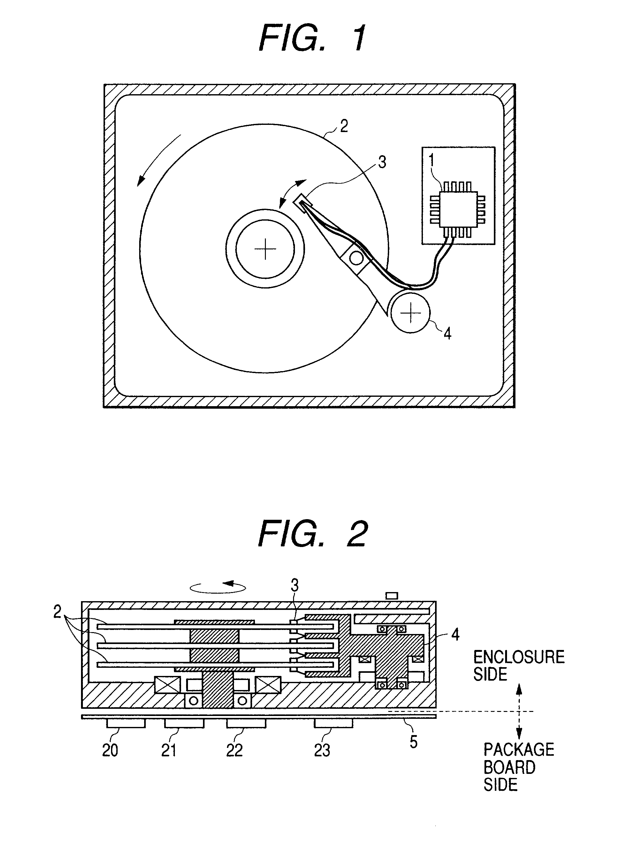
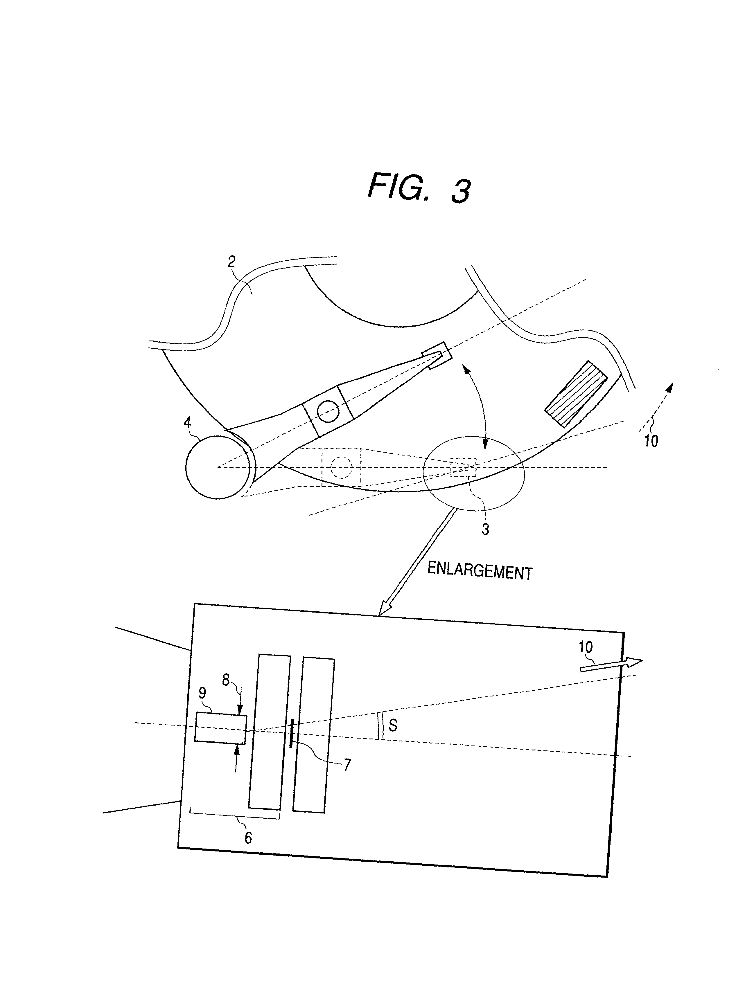
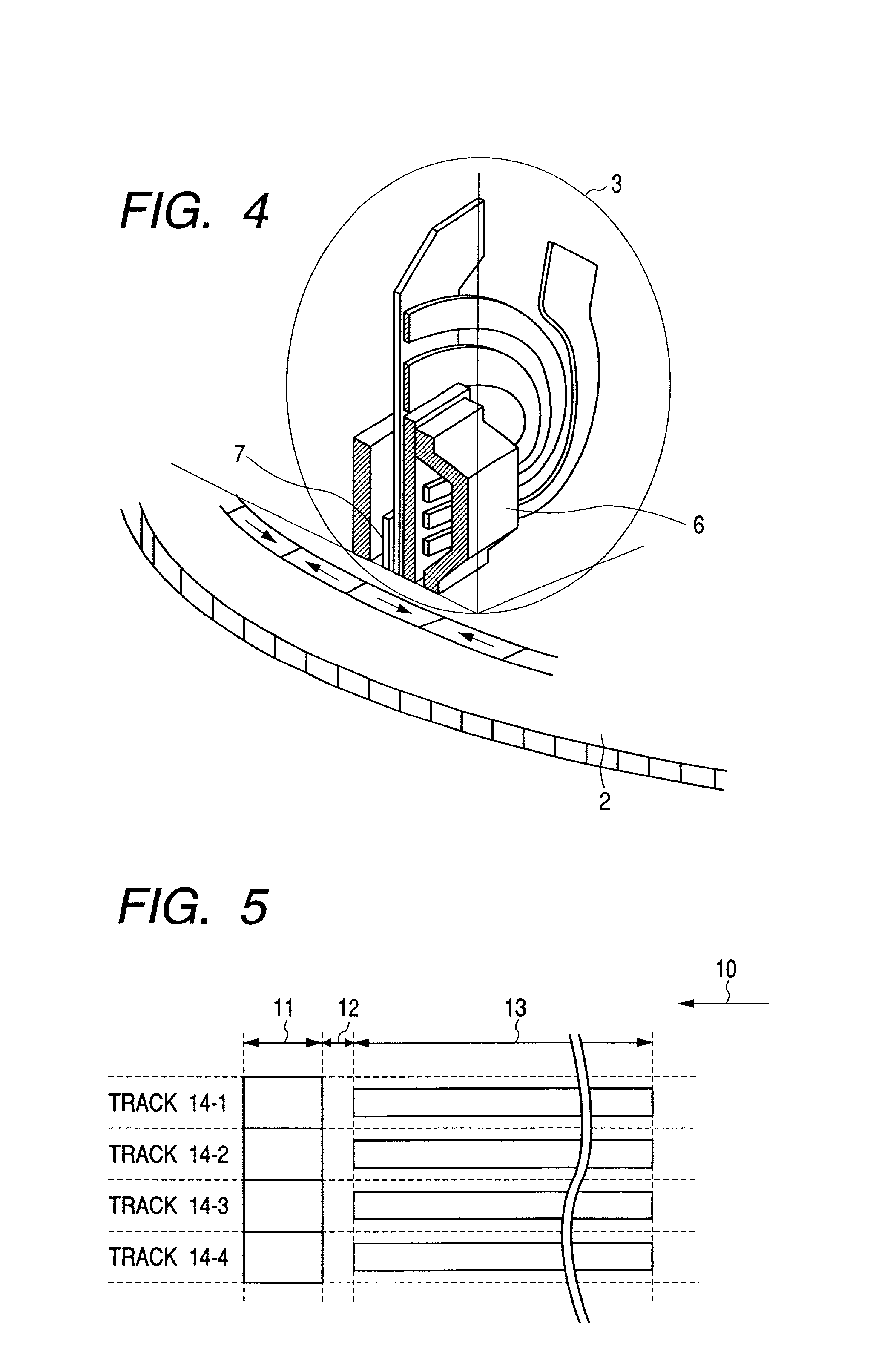
[0001] 1. Field of the Invention[0002] The present invention relates to a method to prevent misread of previously recorded data which are to be overwritten in an information storage apparatus.[0003] 2. Description of the Related Art[0004] The information storage apparatus, e.g., a magnetic storage apparatus, is required to correctly read recorded information in its process of reading written data. But, if an abnormal condition occurs, for example, a significant shock or the like is applied to the apparatus, a write head is heavily displaced from a predetermined track. And, it was found that the recorded information might be misread under the aforesaid abnormal condition. Such a phenomenon (hereinafter called erroneous data) will be described.[0005] FIG. 1 shows a general view of a typical magnetic storage apparatus. The magnetic storage apparatus of FIG. 1 is comprised of a preamplifier 1 which amplifies a read signal, a magnetic recording medium 2 which is fixed to a cylinder for m...

Claims


Application Information

Patent Timeline
IPC IPC(8): G11B5/012G11B19/04G11B20/10G11B20/12
CPCG11B5/012G11B19/04G11B20/10
Inventor TOMIYAMA, FUTOSHIYOSHIDA, HITOSHIHORITA, RYUTAROSAWAGUCHI, HIDEKI
Owner HITACHI LTD
Learn More