Two-piece rotary metal-cutting tool and method for interconnecting the pieces

a metal-cutting tool and two-piece technology, applied in the direction of turning tools, boring/drilling tools, reaming tools, etc., can solve the problems of poor torsion transfer ability, and inability to use known tools

Inactive Publication Date: 2001-10-25
SECO TOOLS AB
View PDF2 Cites 13 Cited by
  • Summary
  • Abstract
  • Description
  • Claims
  • Application Information

AI Technical Summary

Problems solved by technology

This technique however has practical limitations due to handling reasons when it comes to milling and drilling tools which rotate around a lon...

Method used


Image

  • Two-piece rotary metal-cutting tool and method for interconnecting the pieces
  • Two-piece rotary metal-cutting tool and method for interconnecting the pieces
  • Two-piece rotary metal-cutting tool and method for interconnecting the pieces

Examples


Embodiment Construction

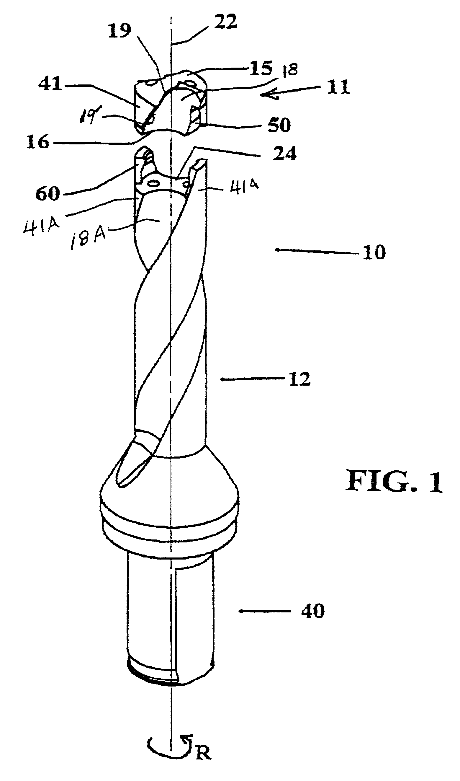
[0022] The embodiment of a tool 10 according to the invention shown in FIG. 1 is a so called helix drill, which comprises a cutting portion or drill tip 11 and a drill body 12. The drill has a rotational direction R.

[0023] The drill tip 11 is provided with at least one cutting edge 19 in the forward end thereof facing away from the drill body 12, which tip is given different designs depending on the area of application.

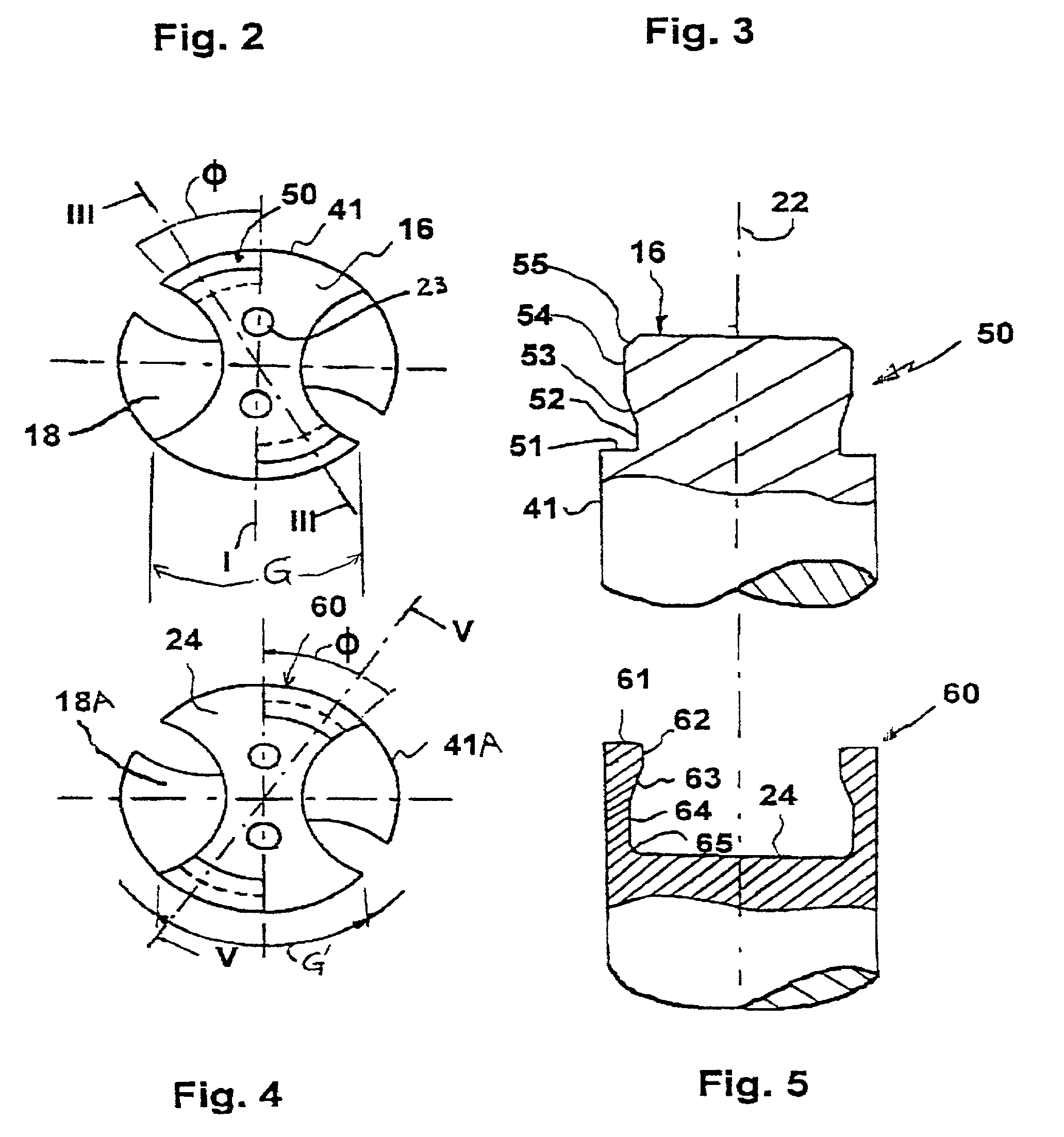
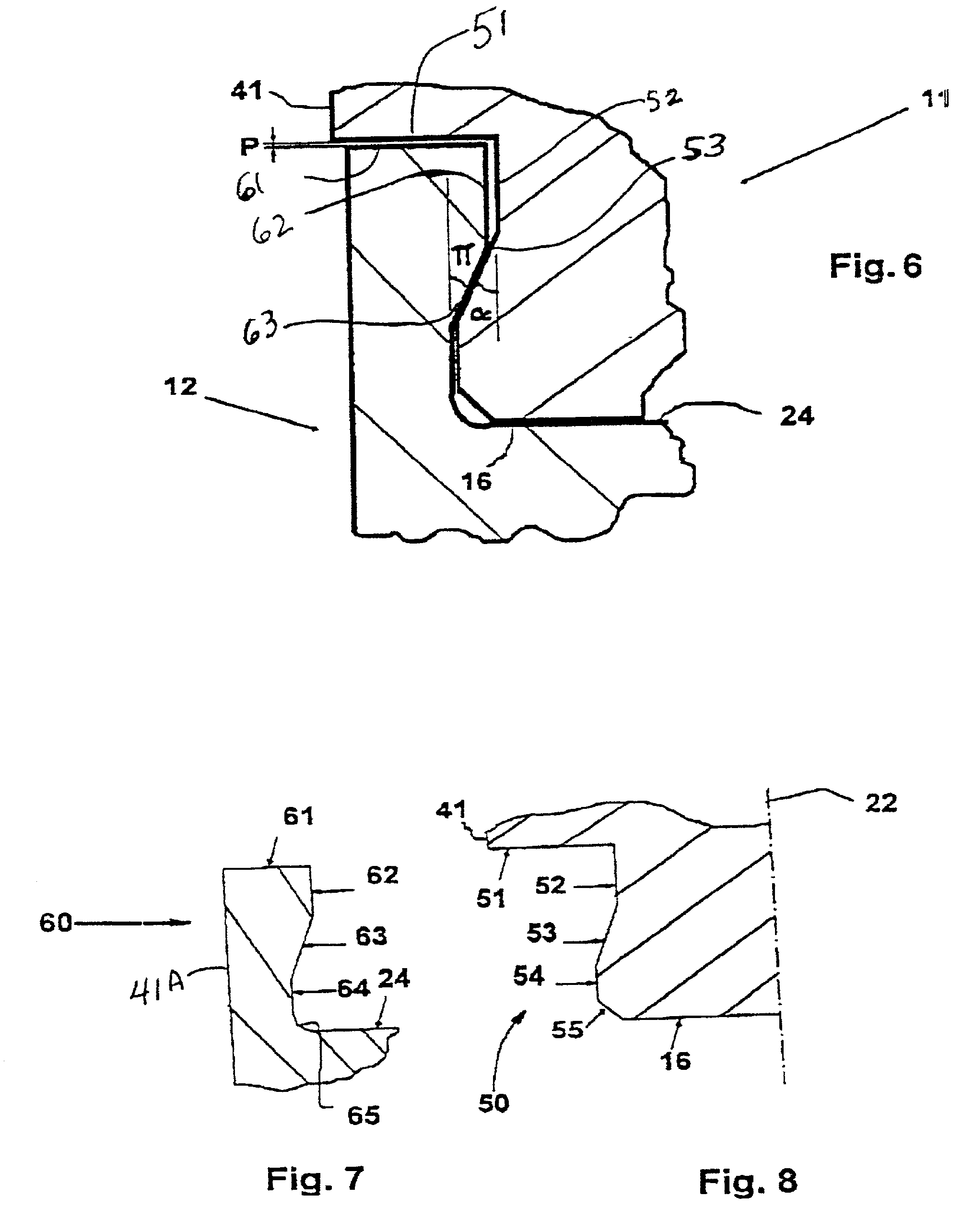
[0024] The drill tip 11 is made of hard material, preferably cemented carbide and most preferably of injection molded cemented carbide, and comprises a front cutting surface formed by two upper clearance faces 15, a lower support surface 16 as well as first and second curved surfaces 41, 18 interconnecting the surfaces 15 and 16. All these surfaces and associated edges are integrated as one piece with the drill tip and consequently formed of the same material, i.e. preferably injection molded cemented carbide. The curved surfaces 18 form front chip flutes for conducti...


PUM

PropertyMeasurementUnit
Angleaaaaaaaaaa
Angleaaaaaaaaaa
Angleaaaaaaaaaa

Abstract

A tool includes a tool body and a cutting portion detachably mounted thereon, the tool being rotatable about a longitudinal center axis. The tool body includes flutes formed in an outer surface thereof, and a pair of forward projections at a front end thereof. The cutting portion includes front flutes formed in an external side thereof, and a pair of recesses extending circumferentially in communication with respective ones of the front flutes. To connect the cutting portion to the tool body, the cutting portion and tool body are converged longitudinally so that the projections enter the front flutes. Then, relative rotation is produced between the cutting portion and tool body to align the front flutes with the rear flutes while causing the projections to enter the recesses and form therewith a bayonet coupling.

Description

[0001] This application is a continuation of application Ser. No. 08 / 929,462, filed Sep. 15, 1997.[0002] The present invention relates to a tool for rotary, cutting machining, comprising a tool body and a cutting portion. The tool body has a front surface, and the cutting portion has a support surface provided to releaseably abut against the front surface in a substantially radial plane. The tool body and the cutting portion comprises means which cooperate for holding them together. The invention also relates to a cutting portion and a tool body as well as a method for mounting a cutting portion to a tool body.PRIOR ART[0003] It is previously known to use interchangeable cutting edges on different types of tools for cutting machining, especially when cutting a metallic workpiece. This technique however has practical limitations due to handling reasons when it comes to milling and drilling tools which rotate around a longitudinal axis.[0004] Through DE-PS-367,010 and Burger U.S. Pat....

Claims


Application Information

Patent Timeline
IPC IPC(8): B23B51/00B23B51/02
CPCB23B51/02B23B2205/02B23B2250/12B23B2251/02B23B2251/14Y10T408/9098Y10T408/78Y10T408/907Y10T408/03Y10T408/89Y10T408/9097B23B2251/50B23B51/00
Inventor BERGLUND, MATTIASLUNDBERG, FREDRICKARBRINK, INGELA
Owner SECO TOOLS AB
Why Eureka
Try Eureka