Method and device relating to battery temperature regulation

a battery and temperature regulation technology, applied in the field of battery temperature regulation, can solve the problems of shortening the operating life of the battery, affecting the service life of the secondary cell, and quickly drying out liquid,

Inactive Publication Date: 2001-10-25
TELEFON AB LM ERICSSON (PUBL)
View PDF0 Cites 54 Cited by
  • Summary
  • Abstract
  • Description
  • Claims
  • Application Information

AI Technical Summary

Problems solved by technology

Furthermore, it is not uncommon for fixed devices to include one or more batteries as a backup in case of a power failure of an external power supply.
If the temperature of the battery is above a preferred operating temperature range associated with the battery, the liquid will quickly dry out and electrodes of the battery will be damaged or worn out.
Peaks in the temperature of the battery, even of relatively short durations, can therefore shorten the operating lifetime of the battery immensely.
If, instead, the battery temperature is below the preferred operating temperature range, a performance of a galvanic process in the battery is degraded, thereby causing a decrease in voltage and charge of the battery.
Consequently, the battery will have to be recharged more often, resulting in a reduction of a lifetime of the electrodes of the battery.
If, due to temperature extremes, the lifetime of the battery is reduced, this will result in increased costs, including costs for a replacement battery as well as working costs for changing the batteries.
However, a drawback is that the ACUs are fairly complicated and expensive.
However, once all of the phase change material has undergone a change of phase, the temperature of the battery will no longer be maintained at the optimal operating temperature.
Furthermore, if there is a sudden change in the ambient temperature, for example from very hot to very cold, the phase change material will completely fail to maintain the battery at its optimal operating temperature.

Method used


Image

  • Method and device relating to battery temperature regulation
  • Method and device relating to battery temperature regulation

Examples


Embodiment Construction

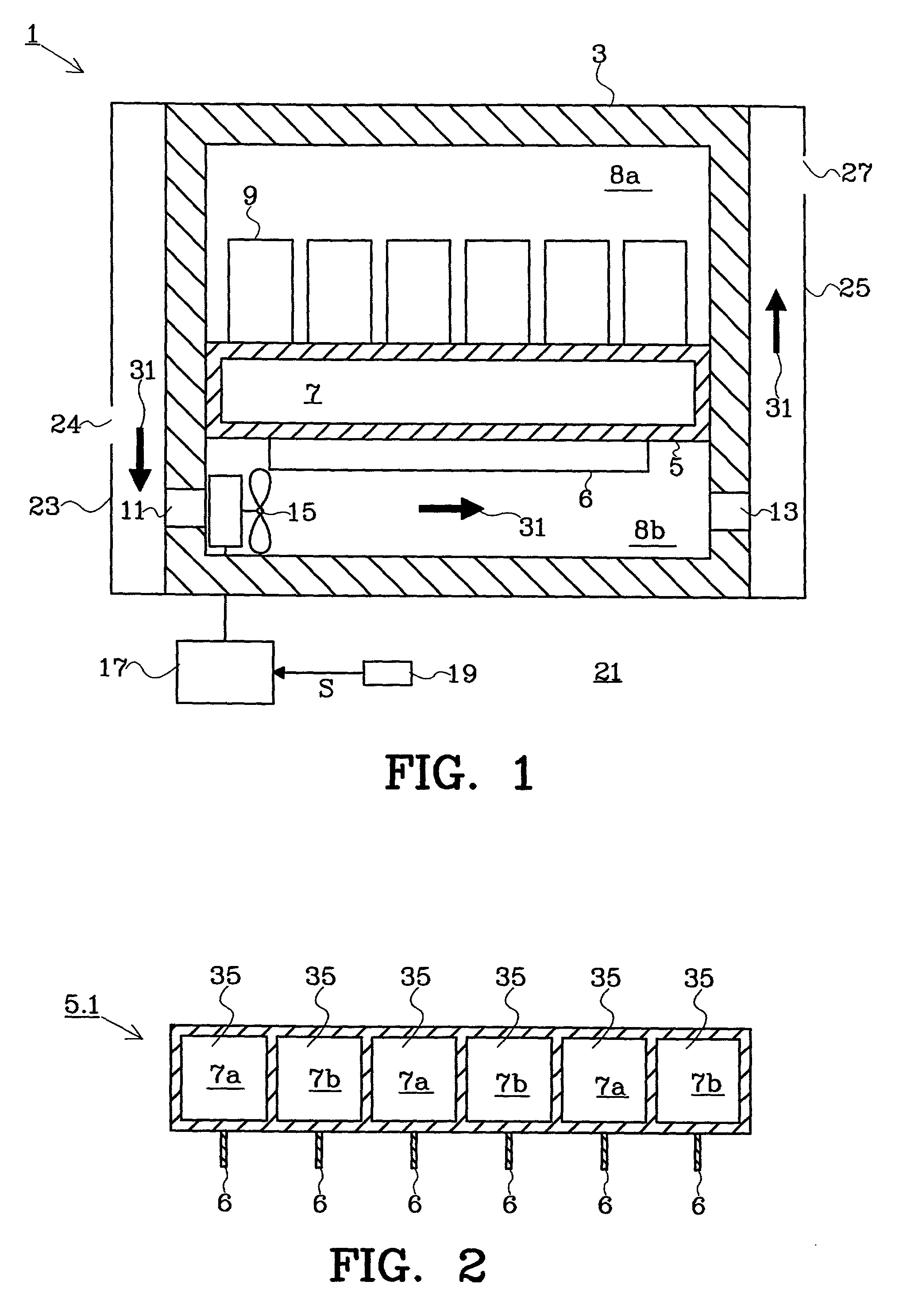
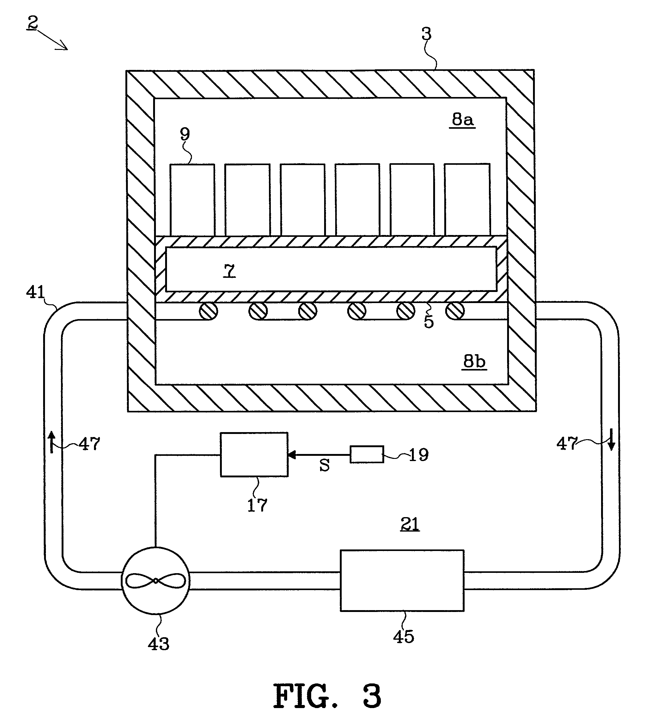
[0018] FIG. 1 is a cross-sectional view of a first device 1 for regulating a temperature of a number of batteries 9. The first device 1 includes a thermally insulating cabinet 3, which defines a space in which a container 5 is arranged. The container 5 is a good thermal conductor and contains a phase change material 7. The container 5, which is relatively flat, is arranged so that it divides the space in the cabinet 3 into a first (upper) section 8a and a second (lower) section 8b, the first and the second sections 8a and 8b being completely sealed off from each other. The batteries 9 are arranged in the first section 8a and are in thermal communication with the container 5 and the phase change material 7 therein. In this example the batteries 9 are arranged in upright positions on top of the container 5. A battery fluid in the batteries 9 is therefore at the bottom of the batteries 9 (i.e. close to the container 5), and this will provide an excellent thermal communication between t...


PUM

PropertyMeasurementUnit
temperaturesaaaaaaaaaa
temperatureaaaaaaaaaa

Abstract

The present invention pertains to the field of methods and devices for battery (9) temperature regulation. Phase change material (7;7a,7b) having a phase change temperature within a preferred operating temperature range is employed in order to maintain the battery temperature within the preferred operating temperature range during extreme ambient temperature conditions. When the temperature of an ambient medium (21) so allows, a transfer of heat between the phase change material (7;7a,7b) and ambient medium (21) is effected for quickly restoring the capability of the phase change material (7;7a,7b) to maintain the battery temperature at the phase change temperature. Otherwise, thermal insulation between the phase change material (7;7a,7b) and the ambient medium (21) is provided.

Description

[0001] The present invention pertains to the field of methods and devices relating to battery temperature regulation, and more particularly to the part of this field concerned with temperature regulation of batteries having a preferred operating temperature range.BACKGROUND AND RELATED ART[0002] Many devices include one or more batteries for use in the operation of the devices. For example, it is common for portable devices to include one or more batteries as a supply of power. Furthermore, it is not uncommon for fixed devices to include one or more batteries as a backup in case of a power failure of an external power supply.[0003] A lifetime of a battery often depends strongly on the temperature of the battery. In most batteries there is an electrolytic process in a liquid solution. If the temperature of the battery is above a preferred operating temperature range associated with the battery, the liquid will quickly dry out and electrodes of the battery will be damaged or worn out....

Claims


Application Information

Patent Timeline
Patent Type & Authority Applications(United States)
IPC IPC(8): H01M10/50
CPCH01M10/5004H01M10/5006H01M10/5024H01M10/5036H01M10/5089H01M10/5057H01M10/5071H01M10/5077H01M10/5087H01M10/5038H01M10/613H01M10/615H01M10/635H01M10/651H01M10/652H01M10/6556H01M10/6565H01M10/6568H01M10/658H01M10/659Y02E60/10
Inventor GUDMUNDSSON, BJORN GUDMUNDHAMMARLING, JAN-OLOF TAGE
Owner TELEFON AB LM ERICSSON (PUBL)
Why Eureka
Try Eureka