

Haptic feedback for touchpads and other touch controls
- Summary
- Abstract
- Description
- Claims
- Application Information
AI Technical Summary
Benefits of technology
Problems solved by technology
Method used
Image

Examples
embodiment 40
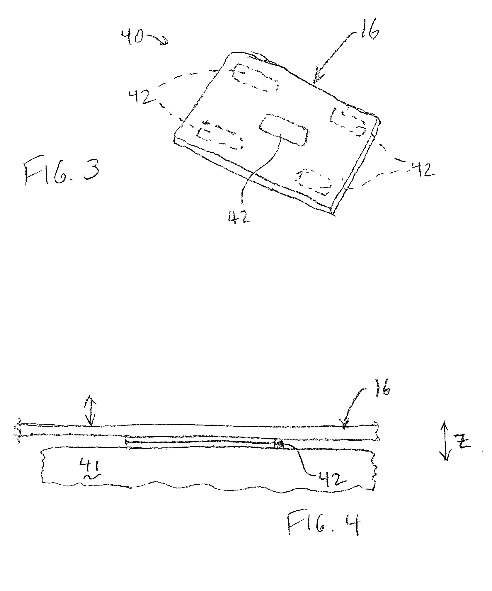
[0040] FIG. 4 is a side elevational view of the touchpad 16 of the present invention as shown in FIG. 3. Touchpad 16 is directly coupled to a grounded piezo-electric actuator 42 which operates to produce a force on the touchpad 16 when an electrical signal is input to the actuator. Typically, a piezo-electric actuator includes two layers which can move relative to each other when a current is applied to the actuator; here, the grounded portion of the actuator remains stationary with respect to the surrounding housing 41 while the moving portion of the actuator and the touchpad move with respect to the housing 41. The operation of piezo-electric actuators to output force based on an input electrical signal is well known to those skilled the art.
[0041] The touchpad 16 can be coupled only to the actuator 42, or can be additionally coupled to the housing of the computer device at other locations besides the actuators 42. Preferably the other couplings are compliant connections, using a ...
embodiment 80
[0071] FIGS. 8a and 8b are top plan and side cross-sectional views, respectively, of another computer device embodiment 80 including a form of the haptic touchpad 16 of the present invention. Device 80 is in the form of a portable computer device such as "personal digital assistant" (PDA), a "pen-based" computer, "electronic book", or similar device (collectively known as a "personal digital assistant" or PDA herein). Those devices which allow a user to input information by touching a display screen or readout in some fashion are primarily relevant to this embodiment of the present invention. Such devices can include the Palm Pilot from 3Com Corp., the Newton from Apple Computer, pocket-sized computer devices from Casio, Hewlett-Packard, or other manufacturers, cellular phones or pagers having touch screens, etc.
[0072] In one embodiment of a device 80, a display screen 82 typically covers a large portion of the surface of the computer device 80. Screen 82 is preferably a flat-panel ...
PUM
 Abstract
Description
Claims
Application Information