Radio receiver and channel estimator

a receiver and channel technology, applied in the field of radio receiver and channel estimator, can solve the problems of large computation capacity of searcher s1, propagation delay variation, and no time alignment between the two sets of fingers

Inactive Publication Date: 2001-11-29
TELEFON AB LM ERICSSON (PUBL)
View PDF5 Cites 46 Cited by
  • Summary
  • Abstract
  • Description
  • Claims
  • Application Information

AI Technical Summary

Problems solved by technology

Due to different propagation delays on the various propagation paths P1-P5, the signal sequence sent from the transmitter will be received by the receiver as a number of versions of the original data stream mutually delayed and thus interfering with each other.
However, this would cost a large computation capacity in the searcher S1 because the length L1 of the window WW1 corresponds to the variation in phase length PHL and thus to the number of combinations of the signal sequence (r) with the delayed conjugate pilot code stream PN.sub.P*.
However, as the radio base stations BTS are positioned at various sites comprising various radio environments the propagation delays vary greatly.
However, to be able to resolve these propagation paths with a great variety in delay, radio base stations BTS would have to be implemented with processor capacity and with a complexity that for most sites will not be needed.
A problem related to a prior art a searcher or a Rake receiver is how to fulfil the conflicting requirements on low complexity and processor capacity on one hand and ability to detect multipath propagation waves with a wide range in propagation delays on the other hand.
However, there is no time alignment between the two sets of fingers.

Method used


Image

  • Radio receiver and channel estimator
  • Radio receiver and channel estimator
  • Radio receiver and channel estimator

Examples


Embodiment Construction

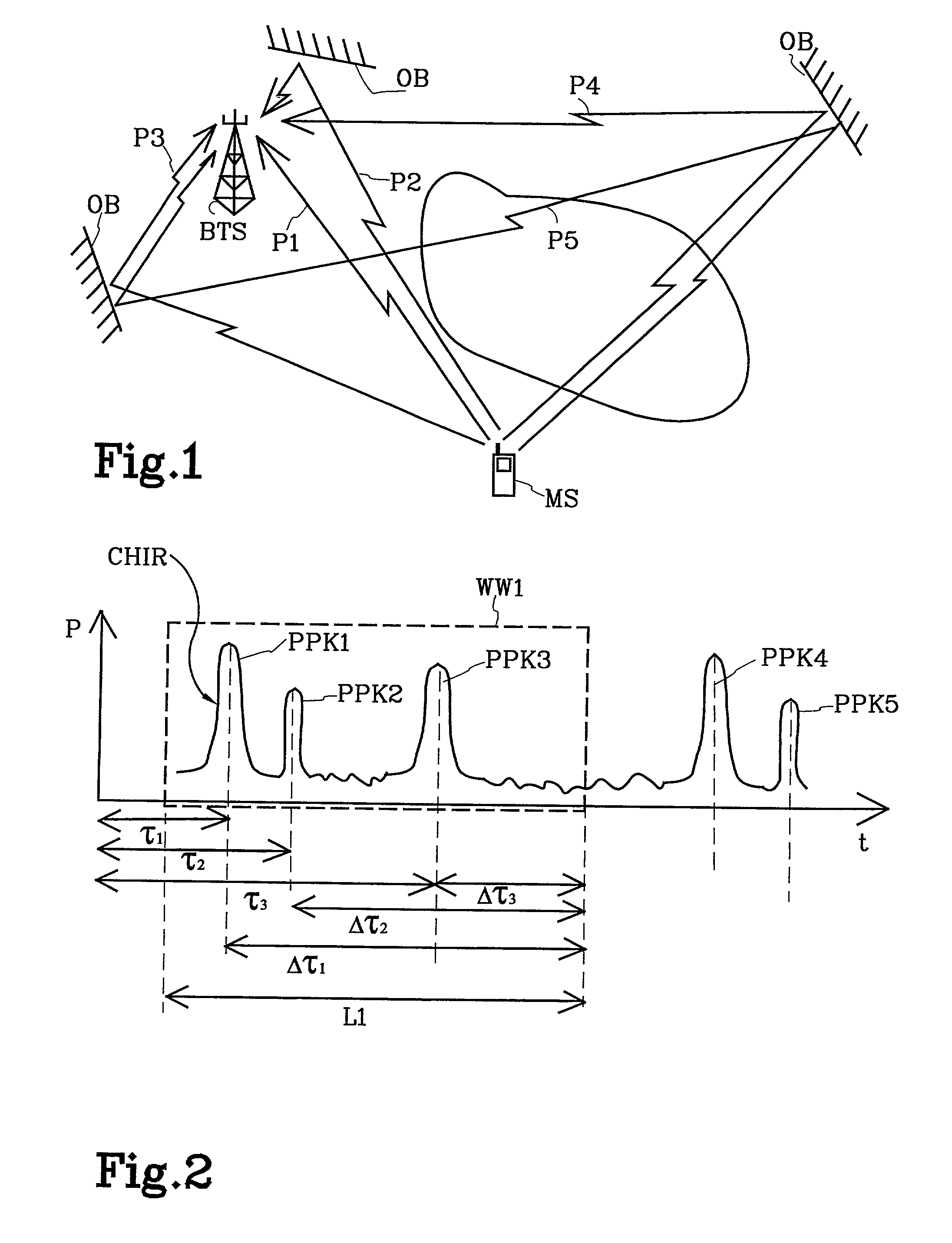
[0037] In FIG. 7, the same diagram over the channel impulse response CHIR as in FIG. 2 is shown, i.e. the channel impulse response CHIR for the radio link from the mobile MS to the radio base station BTS in FIG. 1. However, in FIG. 7 a second window WW2 adjacent of the first window WW1 is indicated. The second window WW2 embraces the last two power peaks PPK4-PPK5 of the channel impulse response CHIR.

[0038] It is an aim of the present invention to configure a searcher and a Rake receiver with additional means to enable detection of propagation paths P4-P5 that are within the second window WW2.

[0039] A radio base station BTS is arranged for handling communication over several radio links, i.e. with several mobile stations MS. FIG. 1 shows by means of example only one mobile station with a radio link, whereby the radio link is represented by its propagation paths P1-P5. If there where more mobile stations MS, radio links established to them would have an own characteristic channel imp...


PUM


Abstract

The present invention is related to a Rake receiver (R1) for receiving a radio signal and to a searcher (S8a, S8b) for estimating the delay profile of one or more radio links. The searcher includes means for estimating delay profiles in separate windows. The searcher is arranged for being switched into a single window mode or alternatively into a multiple window mode. In single window mode the delay profiles of separate radio links are estimated in the windows, while in multiple window mode two or more windows are allocated adjacent in time for estimating the delay profile of the same radio link. Thereby, the use of the resources of the searcher can be adapted to the radio environments in which the searcher will be used. The Rake receiver comprises fingers that are grouped into two sets. Within a set of fingers the propagation paths are time aligned. The output from the two set of fingers are time aligned and then combined.

Description

[0001] The present invention relates to a radio channel estimator and a radio receiver for a spread spectrum signal sequence.DESCRIPTION OF RELATED ART[0002] In FIG. 1 is shown a mobile station MS acting as a transmitter and a radio base station BTS acting as a receiver of a radio transmitted data stream. On the radio link the signal sequence is transmitted over various propagation paths P1-P5, one of the paths P1 in this example is a direct wave from the transmitter to the receiver while on the remaining propagation paths the signal wave is reflected by various obstacles OB. In FIG. 1 for the sake of simplicity just one or two reflections for each wave are shown, however, in practise multi reflections are common.[0003] Due to different propagation delays on the various propagation paths P1-P5, the signal sequence sent from the transmitter will be received by the receiver as a number of versions of the original data stream mutually delayed and thus interfering with each other. A big...

Claims


Application Information

Patent Timeline
Patent Type & Authority Applications(United States)
IPC IPC(8): H04B1/707
CPCH04B1/70754H04B1/7113H04B1/7117H04B2201/7071
Inventor OSTMAN, THOMASFARONIUS, CAROLA
Owner TELEFON AB LM ERICSSON (PUBL)
Why Eureka
Try Eureka