Variable-format web-fed offset printing machine and method of producing variable-format surfaces

Inactive Publication Date: 2002-01-10
MANROLAND WEB SYST
View PDF1 Cites 14 Cited by
  • Summary
  • Abstract
  • Description
  • Claims
  • Application Information

AI Technical Summary

Problems solved by technology

In order to shrink the intermediate sleeves and the printing sleeves on axially, and to remove them, it is disadvantageous to have to provide two separate air supplies on the printing machine.
The air channels running a

Method used


Image

  • Variable-format web-fed offset printing machine and method of producing variable-format surfaces
  • Variable-format web-fed offset printing machine and method of producing variable-format surfaces
  • Variable-format web-fed offset printing machine and method of producing variable-format surfaces

Examples


Embodiment Construction

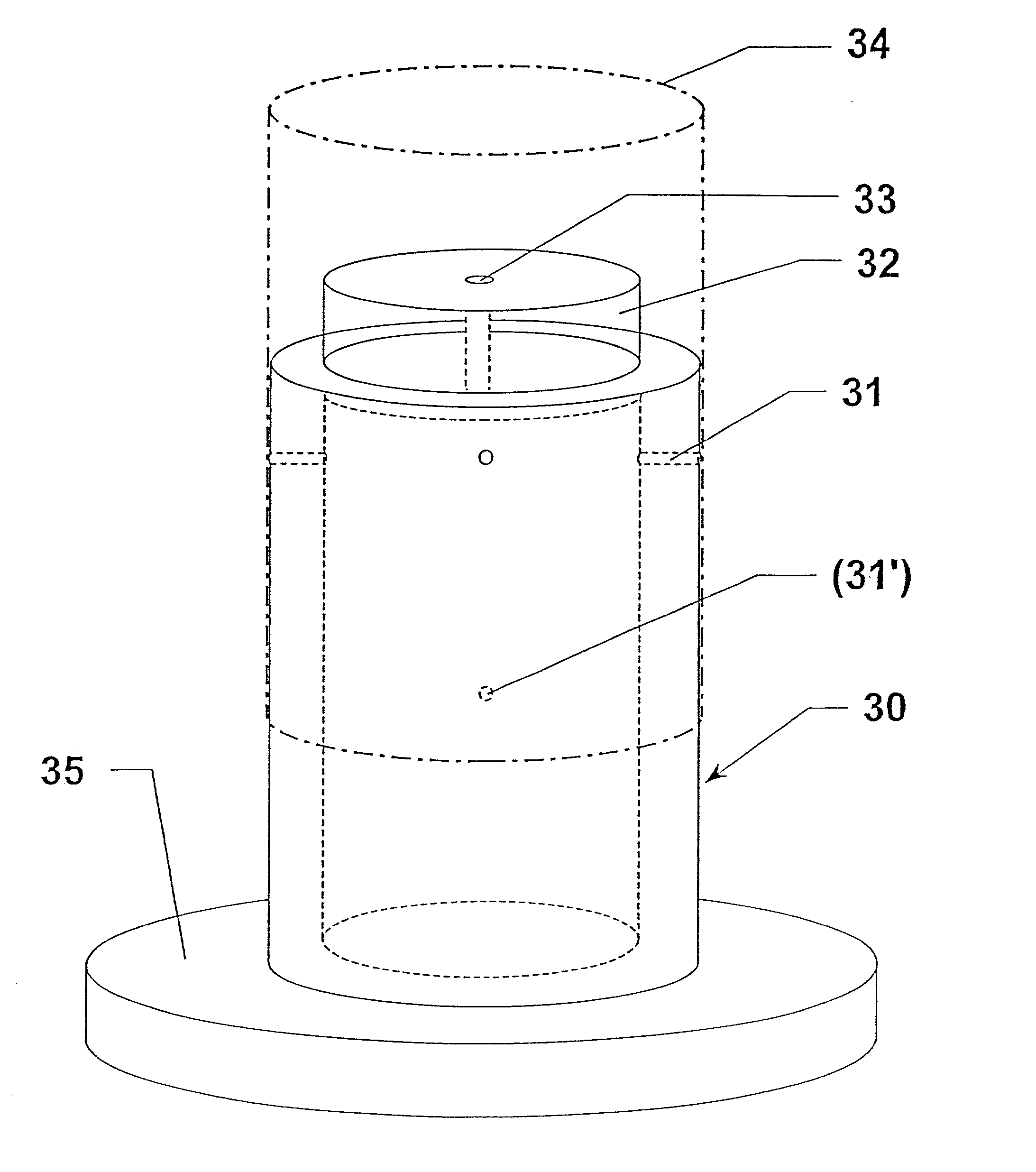
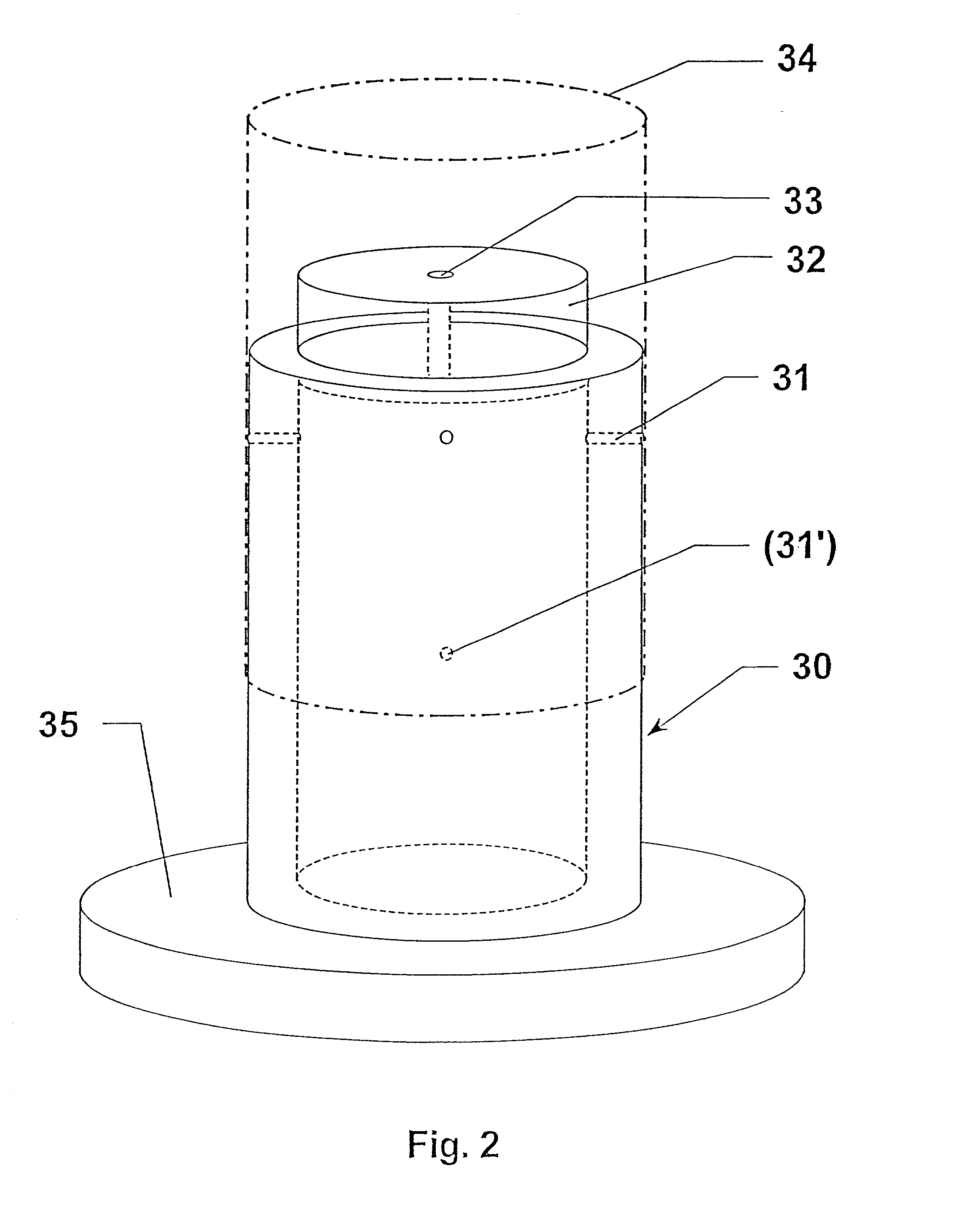
[0039] In variable-circumference web-fed offset printing machines according to the invention, core cylinders are provided on a machine base instead of the conventional fixed-format plate and blanket cylinders, on which core cylinders various intermediate sleeves with different wall thicknesses can be mounted, so that variable-format surfaces are produced. These intermediate sleeves can bear both printing plates and rubber blankets.

[0040] The more extensive equipment of such a machine base with further printing equipment which can be adapted to the various circumferential lengths, such as inking units, damping units or, if appropriate, also in-press image-setting equipment, web guiding systems or folding equipment, will not be discussed further.

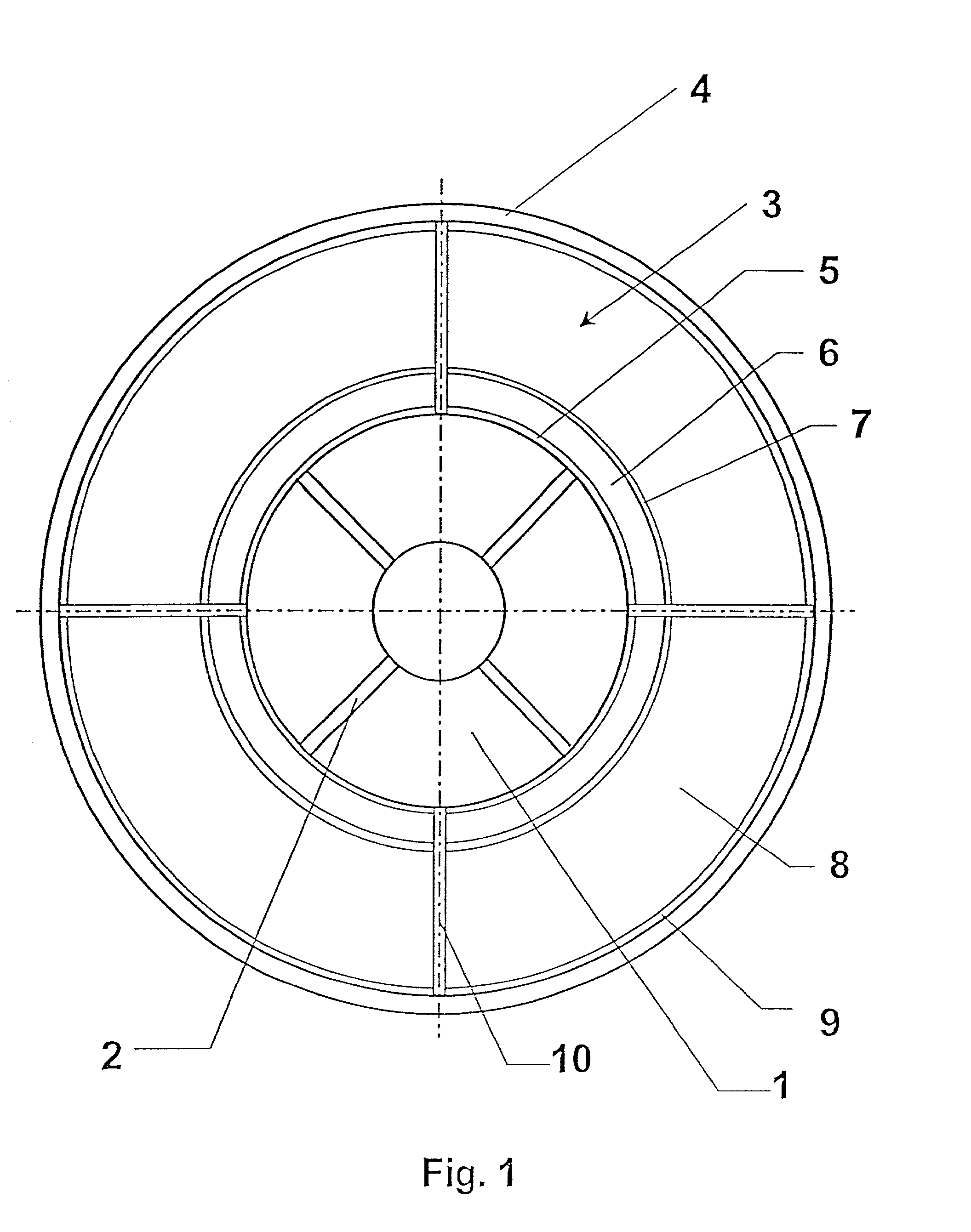
[0041] FIG. 1 illustrates a cross section of an intermediate sleeve (3) mounted on a core cylinder (1). The core cylinder (1) is designed as a conventional air cylinder with compressed-air channels (2) distributed over the circumference, which...


PUM

PropertyMeasurementUnit
Thicknessaaaaaaaaaa
Thicknessaaaaaaaaaa
Thicknessaaaaaaaaaa

Abstract

Variable-format web-fed offset printing machine having printing-unit cylinders comprising core cylinders to which compressed air can be applied and onto which intermediate sleeves can be pushed axially and shrunk on radially. Each intermediate sleeve includes a carrier layer whose inner face rests on the core cylinder, a compressible intermediate layer, a transition layer, and a variable-thickness bridging layer, which ends with a covering layer to which a further surface like a printing plate or a rubber blanket can be fitted.

Description

[0001] 1. Field of the Invention[0002] The invention relates to variable-format web-fed offset printing machines and a method of producing variable-format surfaces.[0003] 2. Description of the Related Art[0004] U.S. Pat. No. 5,819,657 discloses the production of plastic sleeves with various wall thicknesses, which are fitted to core cylinders as intermediate sleeves and bear flexographic or gravure printing plates with different circumferential lengths. The intermediate sleeves are constructed from an inner layer which, under air pressure, expands in the radial direction and compresses a following compressible layer. The compressible layer is followed by a solid transition layer which bears an incompressible bridge layer of different thickness--depending on the format. A printing sleeve with a printing plate may be fitted to a cylindrical terminating layer over the bridge layer.[0005] The intermediate sleeves can be pushed onto a core cylinder by means of compressed air, and the pri...

Claims


Application Information

Patent Timeline
IPC IPC(8): B29C44/12B41F13/10B41F27/10B41F27/14B41F13/08B41N1/16
CPCB29C44/1242B41F13/10B41N1/16B41F27/14B41F27/105
Inventor DILLING, PEERDAUER, HORSTWEINBERGER, MARTIN
Owner MANROLAND WEB SYST
Why Eureka
Try Eureka